
Property characterization of Mn-Si powder porous alloy for semiconductors prepared by solid phase sintering
-
摘要: 以高纯Si粉和Mn粉为原料, 利用固相烧结技术制备得到Mn-Si粉末多孔合金, 对其组织结构及性能进行表征, 分析烧结过程中孔隙形成机理。结果表明: 600℃烧结温度可得到MnSi粉末, 烧结温度升高到1000℃后, 原有的Si与MnSi衍射峰已全部消失, 烧结体中只剩下Mn5Si3物相成分; 烧结体膨胀率和孔隙率都随烧结温度的增加表现出先增加后减小的变化规律, 在烧结温度800℃时取得最大值, 分别为8.86%和54.26%;在Mn颗粒和MnSi相之间存在明显空隙, 随着Si与Mn元素之间扩散的继续, 空隙持续增大进而连通形成层状, 随着烧结温度增加到1000℃, Mn、Si、MnSi被消耗殆尽, 合金中形成Mn5Si3结构。Abstract: The Mn-Si powder porous alloys were prepared by solid phase sintering, using high purity Si powders and Mn powders as the raw materials. The microstructure and properties of Mn-Si powder porous alloys were characterized and the for mation mechanism of pores in sintering process was analyzed. The results show that, the MnSi powders can be obtained at 600℃, with the increase of sintering temperature to 1000℃, the original diffraction peaks of Si and MnSi disappear, only Mn5Si3 phase is present inthe sintered body. The expansion ratio and porosity of the sintered body first increase and then decrease with the increase of sintering temperature, and show the maximum values (8.86% and 54.26%) at 800.℃ There is an obvious gap between Mn particles and MnSiphase, as the diffusion between Si and Mn continues, the gaps increase and then connect to form the lamellar structure; as the sintering temperature rises to 1000, Mn, Si, ℃ and MnSi is used up, the Mn5Si3 structure is formed.
-
Keywords:
- solid phase sintering /
- porous alloy /
- microstructure /
- property characterization
-
多孔合金是一种基体组织中含有特殊孔结构的合金材料,具备比表面积大与透过率高的特点,并且具有优异的吸附性能,已被广泛用于机械、冶金、特种设备等领域[1–4]。按照组成材料的种类进行分类,多孔合金可以被分成无机多孔合金与有机多孔合金两种;同时,又可将无机多孔合金进一步分成金属类无机多孔合金与陶瓷类无机多孔合金[5]。由于有机多孔合金在受到高温作用后会发生破坏,并且较易受到有机溶剂的侵蚀,因此有机多孔合金对于使用环境的要求较高,通常只能适用于比较柔和的工作环境[6]。金属多孔合金具备优异的抗热震性能与较高的力学强度,并且可以对其进行精确加工以及焊接处理,可以获得具有复杂结构的工件,便于实现加工与组装;但是这种金属多孔合金较易受到酸碱介质的腐蚀,并且在空气中受到高温作用后很容易发生表面氧化,无法有效适应强酸碱环境[7–9]。陶瓷多孔合金具备很高的热稳定性,可以在高温环境中使用,不过这种材质缺乏良好的机械加工与焊接性能,较大的限制了工件的加工与组装。粉末冶金多孔合金中价键结构由共价键与金属键共同组成,可同时具备陶瓷多孔合金与金属多孔合金的优势,即具备力学强度高、耐高温、耐酸碱介质及优异的机械加工等性能[10–12]。
多孔结构能降低热电材料的热导率,提升热电性能。多孔半导体材料作为锂电池电极材料能缓解体积膨胀对活性物质的破坏,有效提升电池的循环和倍率性能[13–15]。Mn–Si粉末存在多种二元形式,由于具有较高的导电性被广泛应用于半导体材料。关于Mn–Si半导体材料的报道已有很多,但针对Mn–Si多孔材料烧结体的研究不多。本文利用Si粉、Mn粉为原材料,利用固相烧结方法得到Mn–Si粉末多孔合金试样。对Mn–Si粉末多孔合金组织的物相演变规律及其内部空隙形成机理进行研究,分析Mn–Si多孔合金的形成过程及特点,为分段反应烧结制备Mn–Si多孔合金提供参考依据。
1. 实验材料及方法
实验原料为粒径小于15 μm的Si粉与粒度小于75 μm的Mn粉,两种粉末的纯度都达到99.8%以上。将两种原料粉末按原子比Mn: Si = 7:3混合,采用模压方式在100 MPa压力下把混合粉末压制成ϕ30 mm × 3 mm的圆形坯料,将其放入压力为1×10⁻³ Pa的抽真空钼发热体烧结炉内,并对其实施分段式无压反应烧结处理。对400~1000 ℃范围内不同烧结温度下得到的试样进行测试,各温度下保温时间都为1 h,同时控制升温速率为2.5 ℃·min-1。
按照Archimedes定律对试样孔隙率进行测试;采用D/MAX-3A型X射线衍射仪(X-ray diffraction,XRD)分析Mn–Si多孔合金相变过程以及物相变化;通过SJM-6360VL扫描电镜(scanning electron microscope,SEM)观察Mn–Si多孔合金微观孔结构,并利用电镜自带能谱仪测量合金组元成分及分布情况;使用FBP-3Ⅲ多孔合金性能测试仪表征Mn–Si多孔合金的孔径率及透气性等指标。
2. 结果与分析
2.1 物相分析与显微结构
图 1为采用分段烧结方式在不同烧结温度下得到的各个压坯试样X射线衍射图谱。如图所示,当烧结温度升高至400 ℃时,烧结体内只含有Si与Mn单质,两者并未产生化合反应;随着烧结温度进一步上升到600 ℃,在X射线衍射图谱上同时出现了Mn、Si单质衍射峰与MnSi衍射峰,因此可以推断在烧结阶段最先生成的是MnSi粉末合金。当烧结温度升高到800 ℃时,衍射图谱与600 ℃图谱相近,Mn、Si被不断消耗并转化为MnSi相,在烧结体中同时存在Mn、Si单质以及MnSi、Mn5Si3相;随着烧结温度升高到1000 ℃,原先的Si与MnSi相衍射峰已全部消失,烧结体中只剩下Mn5Si3相。
![]() 图 1 不同烧结温度下Mn–Si粉末多孔合金压坯试样X射线衍射图谱Figure 1. XRD spectra of Mn–Si powder porous alloy at different sintering temperatures
图 1 不同烧结温度下Mn–Si粉末多孔合金压坯试样X射线衍射图谱Figure 1. XRD spectra of Mn–Si powder porous alloy at different sintering temperatures图 2显示了不同烧结温度下Mn–Si粉末多孔合金压坯试样的微观形貌。从图中可以看到,当烧结温度到达400 ℃与600 ℃时,合金基体中的孔隙主要来自于原始粉末堆积空隙;随着温度升高到800 ℃后,组织中已经形成了明显的多孔骨架,此时孔隙率快速增加,并且生成的孔径也较大,相邻颗粒的金属元素在扩散过程中相互结合并转变为冶金结合;当温度到达1000 ℃时,多孔合金发生了明显的致密化,此时烧结体结构快速收缩。
![]() 图 2 不同烧结温度下Mn–Si粉末多孔合金显微形貌:(a)400 ℃;(b)600 ℃;(c)800 ℃;(d)1000 ℃Figure 2. SEM images of Mn–Si powder porous alloy at different sintering temperatures: (a) 400 ℃; (b) 600 ℃; (c) 800 ℃; (d) 1000 ℃
图 2 不同烧结温度下Mn–Si粉末多孔合金显微形貌:(a)400 ℃;(b)600 ℃;(c)800 ℃;(d)1000 ℃Figure 2. SEM images of Mn–Si powder porous alloy at different sintering temperatures: (a) 400 ℃; (b) 600 ℃; (c) 800 ℃; (d) 1000 ℃2.2 膨胀率和孔隙率分析
表 1是在不同烧结温度下制备得到的烧结体膨胀率和孔隙率。通过对比发现,烧结体试样膨胀率和孔隙率变化趋势相同,随烧结温度的增加都表现出先增加后减小的规律,在烧结温度800 ℃时取得最大值,分别为8.86%和54.26%。在600~800 ℃温度范围内,烧结体孔隙率出现了快速上升的现象,在800~1000 ℃温度区间内,孔隙率逐渐减小,发生了致密化。由此可见,在烧结阶段出现的扩散与相变导致合金孔隙改变,引起烧结体膨胀。
表 1 不同烧结温度下Mn–Si粉末多孔合金的膨胀率和孔隙率Table 1. Expansion ratio and porosity of Mn–Si powder porous alloy at different sintering temperatures烧结温度/ ℃ 膨胀率/ % 孔隙率/ % 400 0.62 33.25 600 2.84 38.46 800 8.86 54.26 1000 5.66 51.08 表 2为不同烧结温度下Mn–Si粉末多孔合金的孔径,由表可知,烧结温度提升可获得更大的烧结体孔径。当烧结温度升高至1000 ℃时,冶金结合状态得到显著改善,孔隙率达到51.08%,此时合金平均孔径为10.26 μm,最大孔径为13.86 μm,基体中各粉末颗粒都已完成反应过程;从X射线衍射图谱可以看出,此温度下得到的试样并未生成单质成分,从扫描电镜形貌看出,此时的试样形成了均匀的多孔结构。
表 2 不同烧结温度下Mn–Si粉末多孔合金的孔径Table 2. Pore diameters of Mn–Si powder porous alloy at different sintering temperatures烧结温度/ ℃ 平均孔径/ μm 最大孔径/ μm 400 6.12 11.62 600 5.86 10.86 800 6.84 12.74 1000 10.26 13.85 2.3 孔隙形成分析
根据试样X射线衍射图谱可以发现,当烧结温度低于400 ℃时,Si与Mn没有产生化合反应,孔隙类型主要包括压坯内的原有孔隙与脱出成型剂期间形成的孔隙;当烧结温度到达600 ℃后,压坯中出现了更大的孔隙率。图 3为在600 ℃和1000 ℃烧结温度下Mn–Si粉末多孔合金孔隙显微形貌。从图中可以看到,随着烧结温度的升高,Mn颗粒和MnSi相之间的空隙明显。这些空隙是因为Mn的扩散速度大于Si的扩散速度所造成的,即Kirkendall效应。随着Si与Mn元素之间扩散的继续,空隙持续增大,进而连通形成层状。Mn5Si3主要通过两种反应方式形成:第一种是由Mn与MnSi发生反应得到Mn5Si3;第二种是MnSi的Si扩散到MnSi和Mn之间的界面区域,并和Mn反应得到Mn5Si3。随着烧结温度增加到1000 ℃,Si与Mn元素之间扩散继续进行,此时Mn、Si、MnSi被消耗殆尽,形成Mn5Si3结构。
![]() 图 3 不同烧结温度下Mn–Si粉末多孔合金孔隙显微形貌:(a)600 ℃;(b)1000 ℃Figure 3. Pore morphology of Mn–Si powder porous alloy at different sintering temperatures: (a) 600 ℃; (b) 1000 ℃
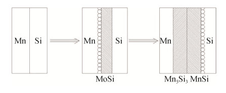
图 3 不同烧结温度下Mn–Si粉末多孔合金孔隙显微形貌:(a)600 ℃;(b)1000 ℃Figure 3. Pore morphology of Mn–Si powder porous alloy at different sintering temperatures: (a) 600 ℃; (b) 1000 ℃Mn–Si粉末多孔合金烧结过程中空隙形成机理主要为压制孔隙演变。根据Mn和Si的扩散速度不同产生的Kirkendall效应,可把Mn–Si粉末多孔合金孔隙形成过程分成三部,如图 4所示:首先,Mn和Si之间没有发生化学反应;随后,随着烧结温度的升高,Mn和Si之间相互扩散,发生冶金结合生成MnSi,由于Kirkendall效应,孔隙率显著提升,并且空隙产生在Mn这一侧;最后,随着烧结温度继续升高,烧结体中生成Mn5Si3成分,空隙产生在Si这一侧。
3. 结论
(1)以高纯Si粉和Mn粉为原料,对其实施分段式无压反应烧结处理。随着烧结温度上升至600 ℃,烧结体中生成MnSi粉末,相邻颗粒的金属元素在扩散过程中相互结合,并转变为冶金结合;烧结温度升高到1000 ℃后,原有的Si与MnSi衍射峰已全部消失,只剩Mn5Si3相衍射峰,烧结体发生了明显的致密化,此时烧结体结构快速收缩。
(2)烧结体膨胀率和孔隙率都随烧结温度的增加表现出先增加后减小的变化规律,在烧结温度800 ℃时取得最大值,分别为8.86%和54.26%。当烧结温度升高至1000 ℃时,冶金结合状态也得到了显著改善,孔隙率达到51.08%,此时合金平均孔径等于10.26 μm,最大孔径等于13.86 μm。
(3)在Mn颗粒和MnSi相之间存在明显空隙,随着Si与Mn元素之间扩散的继续,空隙持续增大,进而连通形成层状。随着烧结温度增加到1000 ℃,Si与Mn元素之间扩散继续进行,此时Mn、Si、MnSi被消耗殆尽,形成Mn5Si3结构。
-
![]()
图 1 不同烧结温度下Mn–Si粉末多孔合金压坯试样X射线衍射图谱
Figure 1. XRD spectra of Mn–Si powder porous alloy at different sintering temperatures
![]()
图 2 不同烧结温度下Mn–Si粉末多孔合金显微形貌:(a)400 ℃;(b)600 ℃;(c)800 ℃;(d)1000 ℃
Figure 2. SEM images of Mn–Si powder porous alloy at different sintering temperatures: (a) 400 ℃; (b) 600 ℃; (c) 800 ℃; (d) 1000 ℃
![]()
图 3 不同烧结温度下Mn–Si粉末多孔合金孔隙显微形貌:(a)600 ℃;(b)1000 ℃
Figure 3. Pore morphology of Mn–Si powder porous alloy at different sintering temperatures: (a) 600 ℃; (b) 1000 ℃
表 1 不同烧结温度下Mn–Si粉末多孔合金的膨胀率和孔隙率
Table 1 Expansion ratio and porosity of Mn–Si powder porous alloy at different sintering temperatures
烧结温度/ ℃ 膨胀率/ % 孔隙率/ % 400 0.62 33.25 600 2.84 38.46 800 8.86 54.26 1000 5.66 51.08  下载: 导出CSV
表 2 不同烧结温度下Mn–Si粉末多孔合金的孔径
Table 2 Pore diameters of Mn–Si powder porous alloy at different sintering temperatures
烧结温度/ ℃ 平均孔径/ μm 最大孔径/ μm 400 6.12 11.62 600 5.86 10.86 800 6.84 12.74 1000 10.26 13.85
下载: 导出CSV
-
[1] 李婷婷, 彭超群, 王日初, 等. Fe-Al、Ti-Al和Ni-Al系金属间化合物多孔材料的研究进展. 中国有色金属学报, 2011, 21(4): 784 https://www.cnki.com.cn/Article/CJFDTOTAL-ZYXZ201104013.htm Li T T, Peng C Q, Wang R C, et al. Research progress in porous Fe-Al, Ti-Al and Ni-Al intermetallic compound porous materials. Chin J Nonferrous Met, 2011, 21(4): 784 https://www.cnki.com.cn/Article/CJFDTOTAL-ZYXZ201104013.htm
[2] He Y H, Jiang Y, Xu N P, et al. Fabrication of Ti-Al micro/nanometer-sized porous alloys through the Kirkendall effect. Adv Mater, 2007, 19(16): 2102 DOI: 10.1002/adma.200602398
[3] De Boor J, Kim D S, Ao X, et al. Temperature and structure size dependence of the thermal conductivity of porous silicon. Europhys Lett, 2011, 96(1): 16001 DOI: 10.1209/0295-5075/96/16001
[4] Kanemitsu Y. Light emission from porous silicon and related materials. Phys Rep, 1995, 263(1): 1 DOI: 10.1016/0370-1573(95)00021-4
[5] Ge M, Fang X, Rong J, et al. Review of porous silicon preparation and its application for lithium-ion battery anodes. Nanotechnolog, 2013, 24(42): 422001 DOI: 10.1088/0957-4484/24/42/422001
[6] Anglin E J, Cheng L Y, Freeman W R, et al. Porous silicon in drug delivery devices and materials. Adv Drug Delivery Rev, 2008, 60(11): 1266 DOI: 10.1016/j.addr.2008.03.017
[7] Dong H X, He Y H, Zou J, et al. Effect of preheating treatment at 575℃ of green compacts on porous NiAl. J Alloys Compd, 2010, 492(1-2): 219 DOI: 10.1016/j.jallcom.2009.12.018
[8] Seitz F. On the porosity observed in the Kirkendall effect. Acta Metall, 1953, 1(3): 355 DOI: 10.1016/0001-6160(53)90112-6
[9] 倪锋, 傅丽华, 邓攀, 等. SiO2-B2O3-Al2O3助焊剂对粉末烧结Cu-C-SnO2多孔材料组织与性能的影响. 粉末冶金技术, 2018, 36(5): 335 DOI: 10.19591/j.cnki.cn11-1974/tf.2018.05.003 Ni F, Fu L H, Deng P, et al. Effects of SiO2-B2O3-Al2O3 scaling powder on microstructures and properties of Cu-C-SnO2 porous materials sintered by powders. Powder Metall Technol, 2018, 36(5): 335 DOI: 10.19591/j.cnki.cn11-1974/tf.2018.05.003
[10] 杨建明, 汤阳, 顾海, 等. 3D打印制备多孔结构的研究与应用现状. 材料导报, 2018, 32(15): 2672 DOI: 10.11896/j.issn.1005-023X.2018.15.020 Yang J M, Tang Y, Gu H, et al. Research and application of 3D printed porous geometric structure: a review. Mater Rev, 2018, 32(15): 2672 DOI: 10.11896/j.issn.1005-023X.2018.15.020
[11] 赵洋, 任淑彬, 王凤林, 等. 铜基高通量换热管内多孔层的制备及性能研究. 粉末冶金技术, 2018, 36(3): 170 DOI: 10.19591/j.cnki.cn11-1974/tf.2018.03.002 Zhao Y, Ren S B, Wang F L, et al. Preparation and properties of porous layer in copper based high flux heat transfer tube. Powder Metall Technol, 2018, 36(3): 170 DOI: 10.19591/j.cnki.cn11-1974/tf.2018.03.002
[12] 邹志欢, 曾凡浩, 刘吉安, 等. 熔渗制备B4C-MgSi复合材料的熔渗动力学、微观结构及力学性能. 粉末冶金材料科学与工程, 2018, 23(3): 252 https://www.cnki.com.cn/Article/CJFDTOTAL-FMGC201803004.htm Zou Z H, Zeng F H, Liu J A, et al. Infiltration kinetics, microstructure and mechanical properties of B4C-MgSi composite fabricated by melt infiltration. Mater Sci Eng Powder Metall, 2018, 23(3): 252 https://www.cnki.com.cn/Article/CJFDTOTAL-FMGC201803004.htm
[13] 张美丽, 解腾飞, 杨超普, 等. 尿素含量对Ti-10% Mg多孔材料孔隙结构和抗压性能的影响. 材料开发与应用, 2018, 33(2): 79 https://www.cnki.com.cn/Article/CJFDTOTAL-CLKY201802014.htm Zhang M L, Xie T F, Yang C P, et al. Effect of urea contents on pore structure and compressive properties of Ti-10% Mg porous materials. Dev Appl Mater, 2018, 33(2): 79 https://www.cnki.com.cn/Article/CJFDTOTAL-CLKY201802014.htm
[14] 付正容, 王修昌, 金青林, 等. 多孔非晶合金及其复合材料的制备技术研究进展. 材料导报, 2018, 32(2): 473 https://www.cnki.com.cn/Article/CJFDTOTAL-CLDB201803019.htm Fu Z R, Wang X C, Jin Q L, et al. A review of the preparation techniques for porous amorphous alloys and their composite. Mater Rev, 2018, 32(2): 473 https://www.cnki.com.cn/Article/CJFDTOTAL-CLDB201803019.htm
[15] 谢锐, 黄峰, 方茜, 等. 熔炼-球磨二步法制备Fe-Mn-Si三元合金. 电池, 2011, 41(3): 135 https://www.cnki.com.cn/Article/CJFDTOTAL-DACI201103004.htm Xie R, Huang F, Fang Q, et al. Preparing Fe-Mn-Si ternary alloy by melting-ball-milling two-step method. Battery Bimonthly, 2011, 41(3): 135 https://www.cnki.com.cn/Article/CJFDTOTAL-DACI201103004.htm
-
期刊类型引用(1)
1. 尤天伢,纪献兵,郭浩,甘园园. 多孔介质结构特征建模与验证分析. 粉末冶金技术. 2023(02): 154-158+166 .  本站查看
本站查看
其他类型引用(1)


计量
- 文章访问数: 247
- HTML全文浏览量: 61
- PDF下载量: 17
- 被引次数: 2
