
Research progress on C-coated Ti composite powders used for preparing high-performance Ti matrix composites
-
摘要:
钛基复合材料中增强相的形貌和分布是决定材料性能的关键,常规粉体机械混合后烧结引入增强相的方式存在形貌难调控、分布单一且均匀性差等问题,导致其强化效果不佳。针对该问题,本团队开发了一系列碳包覆钛复合粉体,通过设计包覆碳源的结构与组成调控粉体烧结过程中增强相的形成路径,不仅实现了增强相形貌调控和不同形貌的组合搭配,而且得到了晶内和晶界双增强相组织,大幅提升了钛基复合材料的力学性能。在此基础上,将碳包覆钛复合粉体拓展应用至钛基复合材料的3D打印领域,解决了高品质复合粉体缺乏并制约其发展的瓶颈问题。总结并评述了碳包覆钛复合粉体在制备钛基复合材料中取得的研究结果与工作进展,为增强相设计与调控提供新的研究思路及技术路线。
Abstract:The morphology and distribution of reinforcements in the titanium matrix composites (TMCs) are crucial in determining the material performances. Due to the uncontrollable morphology and inhomogeneous distribution of the reinforcements in the current TMCs, a series of C-coated Ti composite powders were developed by fluidization technology. By designing the structure and composition of C-coatings, the different morphology combinations and the intragranular/interface reinforcements were both achieved, which significantly improved the mechanical properties of TMCs. Furthermore, the composite powders were also extended to the 3D printing of TMCs, which solved the bottleneck issue of lacking the high-quality composite powders. The research results and work progress of the C-coated Ti composite powders in the preparation of high-performance TMCs were summarized and reviewed, providing the new insight and technical route for the design and control of reinforcements in TMCs.
-
航空发动机正向高功率、大推力的方向发展,涡轮发动机进口温度的提高导致现有高温合金难以满足要求,热障涂层(thermal barrier coatings,TBCs)的应用是提高涡轮发动机工作温度最有效的途径[1–3]。热障涂层多采用双层结构,表层为以ZrO2为主的陶瓷层,陶瓷层与基体之间为MCrAlY粘结层(M为过渡族金属Co、Ni或CoNi)。因性能优异,MCrAlY合金在20世纪中叶就得到广泛的关注。20世纪七八十年代,英、美、德、俄等国的MCrAlY制粉和涂层技术已趋成熟,目前仍被广泛应用和持续改进[4]。国内对MCrAlY的研发起步较晚,与欧美等国存在明显差距。近年来,我国航空业蓬勃发展,对高性能航空发动机的市场需求巨大,MCrAlY合金粉的制备和涂层性能亟待改善。国内外有关MCrAlY涂层性能研究的报道很多,但关于MCrAlY合金粉末制备方面的报道较少,而制备高性能粉末是获得理想涂层的首要条件。北京矿冶研究总院、中科院金属所在气雾化制备MCrAlY合金粉末和合金体系改进方面进行了一些试验探索[1,5]。本文采用紧耦合气雾化技术制备了NiCrAlY合金粉末,研究了粉末形貌、粘结形式、显微组织及元素偏析,分析了凝固组织、颗粒尺寸及冷却速率之间的关系,并讨论了凝固组织、缩孔空洞、元素偏析的产生和变化原因,以期为生产高质量热喷涂用MCrAlY粉末提供实验数据。
1. 实验材料及方法
NiCrAlY合金成分(质量分数)为25.0% Cr、8.0% Al、0.5% Y、0.2% Si,余量为Ni。实验采用真空感应熔炼气雾化(vacuum inert gas atomization,VIGA)工艺,合金粉制备工艺路线为合金原料准备(电解Ni板、Cr块、Al块、Si块和Y锭)→真空感应熔炼→紧耦合气雾化→粉末冷凝→粉末收集→分级→粉末后处理。原料称量后,在真空感应炉镁砂坩埚内布料。冶炼炉通电前,首先使用机械泵和罗茨泵对熔炼室和雾化筒进行抽真空处理,炉料在中频感应炉内熔炼成金属液,控制金属液温度等参数适宜后雾化。采用自行设计的紧耦合气雾化喷盘,导液管材质为氧化锆,内径8 mm。雾化介质为纯氩气、气压3.5 MPa,气体流量>30 m3·min−1。金属液雾化温度1630~1670 ℃,金属液流经中间包底部导液管雾化成熔滴,在雾化筒内冷凝成粉,原粉分级制成各粒度区间样品。
在熔炼工序采用真空感应熔炼装置大大减轻活泼元素Al、Y熔炼的控制难度,减少钢液吸氧和夹杂形成,中频感应炉的电磁搅拌有利于钢液在熔炼期和雾化过程的元素均质化。紧耦合超音速气雾化喷嘴结构如图1所示[6],其中α为喷嘴气流夹角,(°);β为金属导液管的锥顶角,(°);h为金属导液管的突出高度,mm。雾化时,导液管流出的钢液流与高速雾化气流紧密耦合,雾化气流动能转化为钢液滴表面能,在导液管下方形成“V”形气体回流区,有利于熔体成膜和初破碎,促进粉末产品细化。紧耦合气雾化技术与真空感应熔炼工艺组合应用,促使雾化粉末产品具有粒度小、球形度好、成分精准、元素分布均匀、低氧低夹杂等特点。
采用斯科特漏斗测定粉末松装密度与流动性,通过筛分析法测试粒度分布,利用化学滴定法测试化学成分。使用JSM-6400扫描电镜(scanning electron microscope,SEM)检测粉末形貌和分析元素成分。采用德国Bruker公司D8 Discover型3 kW旋转电极X射线衍射仪(X-ray diffraction,XRD)对粉末进行物相分析,X射线源采用Cu靶Kα射线,λ=1.5406 nm,激发电压40 kV,电流40 mA。将样品粉经过机械研磨、抛光和王水腐蚀后制成金相试样,在GX51光学金相显微镜观察微观组织。
2. 结果与讨论
2.1 粉末物理性能
NiCrAlY合金粉的流动性、松装密度和微量元素O、N含量(质量分数)如表1所示。不同粒径粉末的松装密度与流动性明显不同,随粉末粒径减小,松装密度减少,粗中粒径粉末流动性相近且优良,而细粒径粉末流动性急剧恶化。松装密度不仅与合金材质有关,还与粉末形貌和聚集状态紧密相关。对粒径大的粉末,虽然颗粒间隙增大,但颗粒间粘附搭桥现象减少,单位体积内粉末累积间隙体积减小,致使松装密度增大;同理,当粒径小时,虽然颗粒间隙少,但颗粒间容易形成粘附搭桥,致使松装密度减小。当粉末具有较高的松装密度时,喷涂沉积速率高。粉末流动性受粉末形貌、颗粒表面状态、粒度组成等参数影响。同样,当颗粒间有粘附搭桥现象时,既阻碍粉末移动,颗粒表面也易吸附水分和气体,使流动性变差。流动性是影响喷涂过程送粉流畅性的关键参数,较好的流动性有利于喷涂时获得高质量涂层[1,6]。粉末含氧量是原料氧含量、冶炼雾化过程系统真空度以及后处理各工序参数控制状态等因素共同作用的结果。粗颗粒粉由于冷凝时间长,从环境吸氧较多,细颗粒粉由于颗粒总表面积大,总含氧量偏大。表1中不同粒径粉的含氧量也呈现这一规律,细粒径粉末含氧量数值最大,粗粒径次之,中粒径最低。从表1还可以看到,无论粉末粗细,氮含量几乎相同,较为稳定,这可能与氮是熔于固溶体内而非富集在颗粒表面相关。粉末中的O、N等杂质元素,通常会以MxOy或AluNv形式存在,热喷涂时会严重损害涂层结合强度、寿命等,因此粘结层合金粉要严格控制O、N含量。本文未采用氮气而选用高纯氩气为雾化介质,从粉末杂质含量来看,达到预期目的。
表 1 不同粒径NiCrAlY合金粉的物理性能Table 1. Physics properties of the NiCrAlY powders with the different particle sizes粒径 / μm 松装密度 / (g·cm−3) 流动性 / [s·(50g)−1] 质量分数 / % O N 106~297 4.089 18.50 0.0078 0.0043 45~106 4.063 17.37 0.0057 0.0045 25~38 3.850 — 0.0231 0.0047 2.2 粉末粒度分布
合金粉粒度分布受雾化过程影响。紧耦合气雾化过程可分为初次破碎、二次破碎和冷却凝固三阶段[7]。柱状钢液流在气体回流区完成初次破碎后,遵循韦伯数准则We=ρ·v2·d·σ−1,其中ρ为雾化气体密度,v为气体与熔滴之间的相对速度,d为熔滴直径,σ为熔滴的表面张力。当熔滴的韦伯数达到临界值,才可能发生二次破碎,且随韦伯数由小到大,熔滴二次破碎表现为“哑铃式破碎”、“袋式破碎”、“延展式破碎”、“爆炸式破碎”等多种模式,最终得到的粉末粒度差异较大。
图2为NiCrAlY合金粉的区间粒度分布和累积粒度分布曲线。可以看出,85%的粉末粒径小于150 μm。50 μm以下粒度粉末占41%。以累积体积分数50%所对应粉末粒径表示粉末的平均粒度D50,其值大约为58 μm;同理,D84为124 μm。粉末粒度分布宽度δ=D84/D50,可计算得到δ=2.138,表明合金粉粒度区间较宽,分布不均匀。热障涂层粘结底层材料需要根据喷涂工艺、陶瓷粉参数、应用领域以及粉末综合参数选用某一粒度区间的粉末,其粒度分布与雾化气压、导液管内径、钢液过热度等工艺参数紧密相关,可通过调整雾化参数改变收得粉末的粒度分布。
![]() 图 2 NiCrAlY合金粉的粒度分布Figure 2. Cumulative particle size distribution (volume fraction) and the particle size of the NiCrAlY powders
图 2 NiCrAlY合金粉的粒度分布Figure 2. Cumulative particle size distribution (volume fraction) and the particle size of the NiCrAlY powders2.3 粉末形貌
图3为不同粒度NiCrAlY合金粉的形貌。从图3可以看出,不论粒径大小,粉末主要由球形或近球形颗粒组成,均含有少量的异形颗粒。合金粉末粒度越细小,颗粒球形度越好,表面也越光滑。随粒径增大,粉末球形度变差,形貌更近泪滴状,颗粒表面褶皱突起和卫星颗粒增多,光滑度变差。
![]() 图 3 不同粒度NiCrAlY合金粉显微形貌:(a)<20 μm;(b)25~38 μm;(c)45~90 μm;(d)120~200 μmFigure 3. SEM images of the NiCrAlY powders with the different particle size: (a) <20 μm; (b) 25~38 μm; (c) 45~90μm; (d) 120~200 μm
图 3 不同粒度NiCrAlY合金粉显微形貌:(a)<20 μm;(b)25~38 μm;(c)45~90 μm;(d)120~200 μmFigure 3. SEM images of the NiCrAlY powders with the different particle size: (a) <20 μm; (b) 25~38 μm; (c) 45~90μm; (d) 120~200 μm从图3(a)和图3(b)可以看出,细小粉末(微米级)多为单颗粒状态,随粒径略增大,部分粉末发生粘连。这是因为微米级颗粒冷却快,碰撞前已完全凝固,在飞行冷却中不易相互粘结。粘连颗粒多呈“包覆式”粘连和“葫芦式”粘连,“包覆式”粘连是由包覆在内的颗粒先凝固成形,随后另一熔滴撞击在此颗粒上,熔滴发生延展和冷凝;“葫芦式”粘连是两个凝固颗粒中至少有一个未完全凝固,两者碰撞时局部粘连形成。这两种粘连在颗粒直径相差不大时,发生几率较多[8‒9]。紧耦合气雾化的“V”型气体回流区较小,但回流区内发生钢液柱→液膜→熔滴的初次、二次破碎,流场结构十分复杂[7],大大加剧不同尺寸熔滴冷凝中相互粘连的几率。从图3(c)和图3(d)可以看出,随粒度变大,带卫星颗粒的粉末明显增多,许多大粉末甚至有多个卫星颗粒,此时粘连方式主要是“凸起式”粘连。一般认为,“凸起式”粘连是快速凝固的小颗粒与表面仍未完全凝固的大颗粒发生碰撞而粘接在一起。
通常认为,粘连粉末与气雾化参数紧密相关。雾化喷盘结构、气压、气温、气体流量,雾化筒内气体回流场尺寸、排气速率等均是影响因素。结合表1中数据可看出,细颗粒粉末虽有较好的球形度,颗粒表面光滑,可是粉末流动性差,松装密度低。粗颗粒粉虽球形度差,颗粒表面有严重的褶皱起伏和卫星颗粒,然而粉末有较好的流动性,松装密度高。这也再次表明,松装粒度和流动性不仅与粉末形貌和表面有关,还受粉末的粒度分布和聚集状态等参数影响。
2.4 粉末显微结构
图4为不同粒度NiCrAlY合金粉末颗粒断面显微组织。粉末内部组织既反映了合金的凝固状态,也体现了凝固过程中合金的结晶和长大状况。从图4可以看出,粉末颗粒具有胞状晶和树枝晶两 种典型组织,不同尺寸颗粒均为胞状晶+树枝晶的混合体。
![]() 图 4 不同粒度NiCrAlY合金粉末断面显微组织:(a)250 μm;(b)160 μm;(c)80 μm;(d)30 μmFigure 4. Cross-section microstructure of NiCrAlY powders with different particle size: (a) 250 μm; (b) 160 μm; (c) 80 μm; (d) 30 μm
图 4 不同粒度NiCrAlY合金粉末断面显微组织:(a)250 μm;(b)160 μm;(c)80 μm;(d)30 μmFigure 4. Cross-section microstructure of NiCrAlY powders with different particle size: (a) 250 μm; (b) 160 μm; (c) 80 μm; (d) 30 μm由图4(d)可见,粒径小于30 μm的粉末内部主要是胞状晶组织,但已经出现少量树枝晶组织,颗粒截面内可观察到少量凝固缩孔。随粉末粒径增大,如图4(b)和图4(c),凝固组织由胞状晶+树枝晶组成,胞状晶呈放射状生长,与图4(d)相比,树枝晶比例明显增多,且树枝晶生长趋于完整,晶粒更加粗大,颗粒内明显可见分散着一些凝固缩孔。随粉末颗粒尺寸继续增大,从图4(a)可见,粉末显微组织以树枝晶为主,部分树枝晶还出现二次晶组织,胞状晶仅在局部区域内存在。对比图4(b)发现,颗粒内出现的凝固孔洞数目更多,尺寸明显增加。
从图4还可看出,无论粉末粒径大小,截面边缘主要为胞状晶组织,树枝晶主要出现在靠近颗粒截面中间的位置,同时,粉末内部的胞状晶和树枝晶的晶粒尺寸都极不均匀。熔滴冷却速度是影响粉末内部组织的关键参数。金属熔滴的凝固是一个高温高速过程,涉及从液态熔体到固态的转变,直接测量熔滴冷凝速度是相当困难的,通常采用间接法推导。二次树枝晶臂距与冷却速率之间的关系为λ=b·T−n,其中λ为二次枝晶臂距,μm;T为冷却速率,K·s−1;b为修正常数,μm∙(K∙s‒1)n;n取值为1/3~1/2[10]。采取“截线法”[11],在图4中随机量取6~8个胞晶或枝晶间距,取测量值的平均值作为晶间距,取b=50 μm∙(K∙s‒1)n,n=0.33,推导颗粒冷速。不同尺寸颗粒的晶间距和冷速数据见表2所示。
表 2 不同粒度NiCrAlY粉末的晶间距和冷速Table 2. Grain spacing and cooling rate of the NiCrAlY powders with different particle sizes粉末粒度 / μm 晶间距 / μm 颗粒冷速 / (K·s−1) 251.5 3.144 4020 145.9 2.456 8400 72.9 1.500 37000 40.6 1.350 51000 25.5 1.229 67000 NiCrAlY合金主元素Ni、Cr、Al的熔点、原子半径、密度差距明显,熔滴冷凝过程中趋向发生选择性凝固,形成树枝晶组织,所以小粒径粉末内也出现明显的枝晶组织。随熔滴增大,冷速降低,大粒径粉末趋向形成树枝晶组织。但是大熔滴内不同部位与环境之间热交换较为复杂,情况各异。因此,图4的大粒径粉末内才会出现细化胞状晶和枝状晶的混合组织,甚至出现二次枝晶。
不同粒径粉末的表面光洁度也受凝固冷速影响。如图3所示,粒径小的粉末冷凝速率高,使得熔滴内结晶过程受到抑制,冷凝后熔滴表面只有轻微收缩,所以粉末表面光洁;大颗粒粉末冷速低,冷凝时间长,冷凝中容易形成凝固收缩差异,使大粒径粉末表面光洁度较差[12]。
图5是NiCrAlY粉末(45~106 μm)断面的扫描电镜背散射(scanning electron microscope-back scattered electron,SEM-BSE)形貌。从图5(a)可知,组织整体均匀致密,具有缩孔或空心缺陷的粉末数量占比约为8%~10%。观察单个放大颗粒发现[12],截面直径<50 μm粉末内部结构致密,未观察到明显的冶金缺陷,如图5(b)所示。部分截面直径>50 μm的粉末内出现不规则的凝固缩孔,大粒径颗粒内甚至出现多处缩孔,如图5(c)所示。这是因为冷凝过程中小尺寸熔滴冷速快、过冷度大,促进内部大量形核,晶粒之间相互接触而抑制晶粒长大。大尺寸熔滴冷速慢、凝固时间长,易形成树枝晶组织。凝固缩孔是由于熔滴冷凝收缩形成的,当大粒径颗粒内形成多个树枝晶,冷凝收缩程度更大,易形成多处缩孔[13]。
![]() 图 5 粒径为45~106 μm的NiCrAlY粉末断面扫描电镜背散射电子形貌:(a)粉末显微组织;(b)无缺陷颗粒;(c)凝固缩孔颗粒;(d)空心颗粒Figure 5. SEM-BSE images of the NiCrAlY powders in the cross-section with the particle size of 45~106 μm: (a) overall microstructure of the powders; (b) featureless structure powder; (c) solidification shrinkage; (d) hollow defects
图 5 粒径为45~106 μm的NiCrAlY粉末断面扫描电镜背散射电子形貌:(a)粉末显微组织;(b)无缺陷颗粒;(c)凝固缩孔颗粒;(d)空心颗粒Figure 5. SEM-BSE images of the NiCrAlY powders in the cross-section with the particle size of 45~106 μm: (a) overall microstructure of the powders; (b) featureless structure powder; (c) solidification shrinkage; (d) hollow defects在截面直径>50 μm的颗粒内还观察到空心缺陷,空心主要出现在颗粒中心部位,如图5(d)所示。紧耦合雾化时,受韦伯系数(We)影响,液柱破碎可能发生初次破碎或二次破碎。研究表明,当满足12<We<50,二次破碎易发生“袋式(Bag)破碎”模式。随液膜快冷,钢液的表面张力迅速上升,阻碍液膜继续破碎,并可能将雾化气包裹,熔滴冷凝后就会形成空心缺陷。当粉末粒径大时,首先是容易满足发生“袋式破碎”的韦伯系数条件,其次是颗粒由铺展面积更大的液膜冷凝生成,更增加包裹气泡形成空心粉的发生几率[14]。
合金粉内出现凝固缩孔和空心缺陷是由合金成分、制备工艺和凝固机理共同作用造成的,难于彻底消除。制备热障涂层时,若粘结底层粉末中缩孔或空心不能消除,包裹的气体不能逸散,对涂层结合强度、孔隙度等指标是有影响的。冷却速率是影响粉末显微组织的关键因素,晶体组织状态的形成,凝固缩孔和空心缺陷的形成都受其作用,而冷速又受雾化器结构和雾化工艺参数的影响。
2.5 粉末内部元素的偏析
由于粉末将成分偏析锁定在单个颗粒内,解决了传统冶金产品的宏观偏析,但粉末颗粒内部元素的富集和贫化、晶胞内外的偏析也会影响粉末性能的稳定。
图6是NiCrAlY合金粉末断面的能谱(energy disperse spectroscope,EDS)面扫描分析。从图6可以看出,主要元素Ni、Cr、Al均匀分布,没有明显的富集和贫化现象,而微合金化元素Y、Si则分布不均匀。主要元素均匀分布是由于熔融液滴雾化过程中处于103~104 K·s−1冷速下,粉末内部元素来不及聚集,就已快速凝固所致。
![]() 图 6 NiCrAlY合金粉末断面能谱分析Figure 6. EDS mapping of the NiCrAlY powders in the cross-section
图 6 NiCrAlY合金粉末断面能谱分析Figure 6. EDS mapping of the NiCrAlY powders in the cross-section为进一步探明粉末内部晶胞元素分布,利用扫描电镜及能谱对NiCrAlY合金粉进行元素测定,测量位置如图7(a)所示,对区域A进行面扫描,探测晶内B点、晶界C点、晶间D点元素分布。图7(b)和图7(c)为晶内B点和晶界C点的能谱分析,各元素含量数据见表3。由表3可知,与区域A面扫描均值相比,晶界C点Si、Y含量偏高,Al含量偏低,晶内B点表现相反。各测试点Cr、Ni含量基本一致,表明晶界和晶内存在轻微的元素偏析现象[15‒16]。研究表明[2],Si、Y在NiCrAlY合金固溶度较低,当金属液元素含量高及熔滴低速冷凝时,就可能发生元素偏析。Si可降低热障涂层的氧化速率,提高氧化膜黏附强度和高温抗氧化性能。Y可细化晶粒,提高热障涂层氧化膜和基体的结合力。Si、Y在晶界处发生富集偏析可起到阻碍晶界移动、提高热障涂层结合强度的作用。
![]() 表 3 图7(a)中各点能谱分析Table 3. EDS analysis of each spots in Fig.7(a)
表 3 图7(a)中各点能谱分析Table 3. EDS analysis of each spots in Fig.7(a)位置 质量分数 / % Al Si Y Cr Mn Ni 能谱面扫A 6.42 0.57 0.48 28.06 — 64.47 晶内B 9.05 0.21 0.29 27.15 — 63.30 晶界C 5.63 1.02 1.65 27.02 0.75 63.93 晶间D 6.65 0.67 0.58 27.74 0.39 63.96 名义含量 7.82 0.32 0.57 25.70 — 65.59 图6、图7和表3的数据表明,NiCrAlY合金粉主元素分布均匀,微合金化元素Si、Y分布不均匀,存在偏析。要抑制此种偏析较为困难。小粒径颗粒还可依靠高凝固冷速抑制合金元素扩散,弱化偏析。对于冷速较低的大尺寸粉末,措施就少得多。
2.6 粉末的相结构
图8是不同粒度NiCrAlY粉末的X射线衍射图谱。如图所示,不同粒度粉末的物相组成基本相同,主要由γ'-Ni3Al、γ-Ni、α-Al2O3、Cr2O3相组成,形成γ'+γ相结构。由于冷速不同,不同粒度粉末的相组成和晶体结构可能存在差异[17]。随粉末粒度减小,衍射曲线中γ-Ni(2θ=45°)衍射峰强度和面积逐渐增强,表明其含量明显增加[18]。如图8(b)所示,随粉末粒度减小,γ'-Ni3Al(2θ=52°附近)的峰位向小角度方向发生了偏移倾斜,这是由快速凝固形成过饱和固溶体效应造成的。粒径<20 μm的NiCrAlY粉末冷速最大,发生的偏移程度也最大,晶格畸变也最严重,反映出凝固速率越高,γ'-Ni3Al固溶体里的溶质原子饱和度越高[19‒20]。
![]() 图 8 不同粒度NiCrAlY粉末X射线衍射图谱Figure 8. XRD patterns of the NiCrAlY powders with the different particle sizes
图 8 不同粒度NiCrAlY粉末X射线衍射图谱Figure 8. XRD patterns of the NiCrAlY powders with the different particle sizes3. 结论
(1)采用紧耦合气雾化技术制备NiCrAlY合金粉末,大部分粉末(约85%)粒径小于150 μm,以球形和近球形颗粒为主。随粒度增大,球形度变差,粘连和卫星颗粒现象严重。
(2)粉末显微组织主要由树枝晶和胞状晶组成,直径25~250 μm熔滴的凝固冷速为4000~67000 K·s−1。
(3)小粒径粉末(粒径<50 μm)内部结构致密,少量大粒径(粒径>50 μm)粉末内部出现凝固缩孔和空心,粉末颗粒晶界和晶内存在元素Si、Y偏析。
(4)粉末相组成主要为γ'-Ni3Al和γ-Ni,且晶格畸变程度随粒度变小而加重。
-
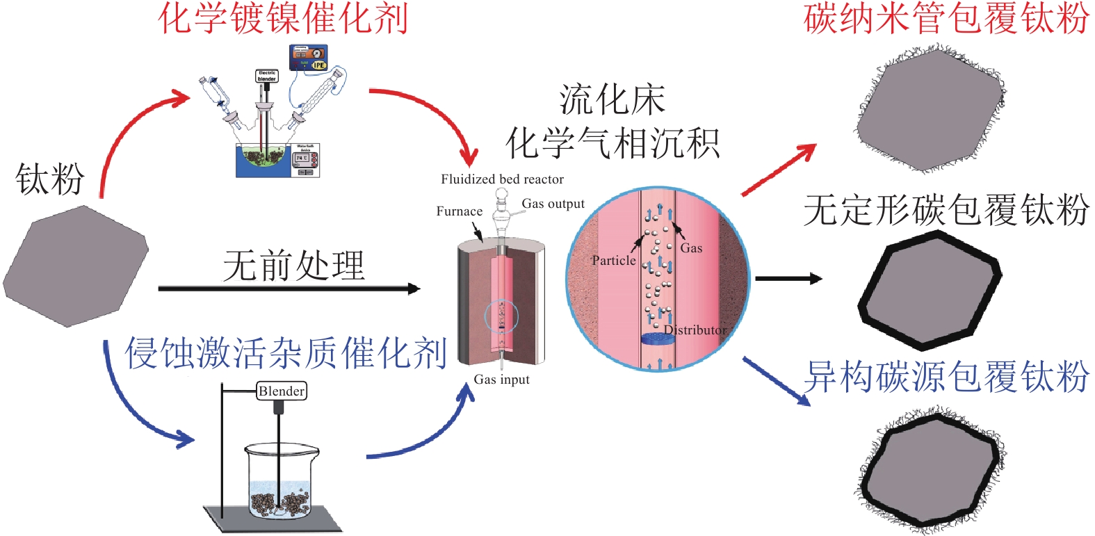
![]()
图 1 不同类型碳包覆钛复合粉体的制备方法示意图
Figure 1. Schematic diagram of the fabrication process for the different C-coated Ti powders
![]()
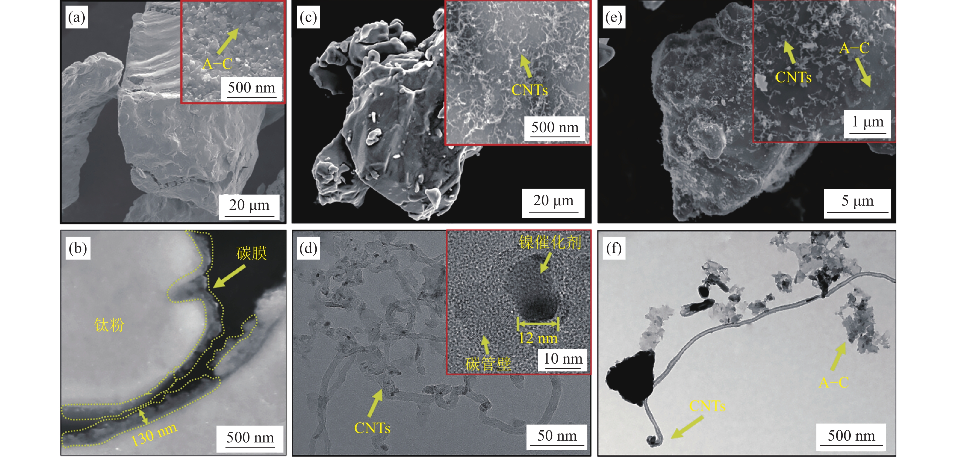
图 2 不同碳包覆钛粉体显微形貌[29‒32]:(a)A–C/TC4粉的表面微观形貌;(b)A–C/TC4粉的截面微观形貌;(c)CNTs/Ti粉的微观形貌;(d)CNTs的透射电镜图片;(e)H–C/TC4粉的微观形貌;(f)两种碳源的透射电镜图片
Figure 2. Morphologies of the different C-coated Ti powders[29‒32]: (a) SEM image of the A–C/TC4 powder surface; (b) sectional SEM image of the A–C/TC4 powder; (c) SEM image of CNTs/Ti powder; (d) TEM image of the extracted CNTs; (e) SEM image of H–C/TC4 powder; (f) TEM image of the extracted CNTs and A–C
![]()
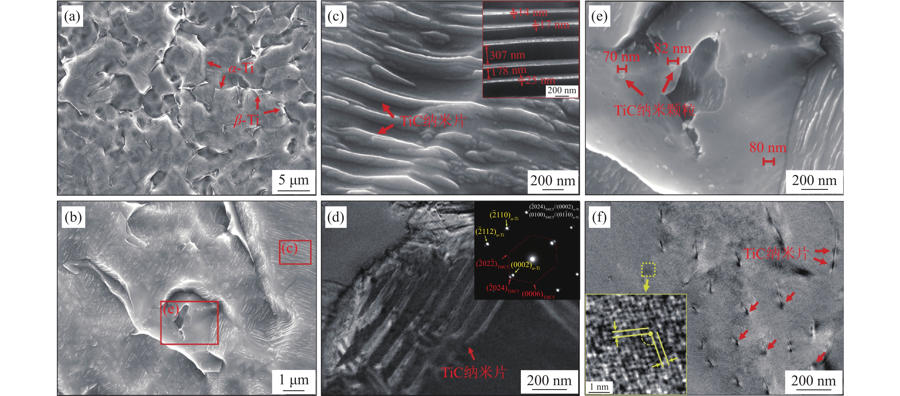
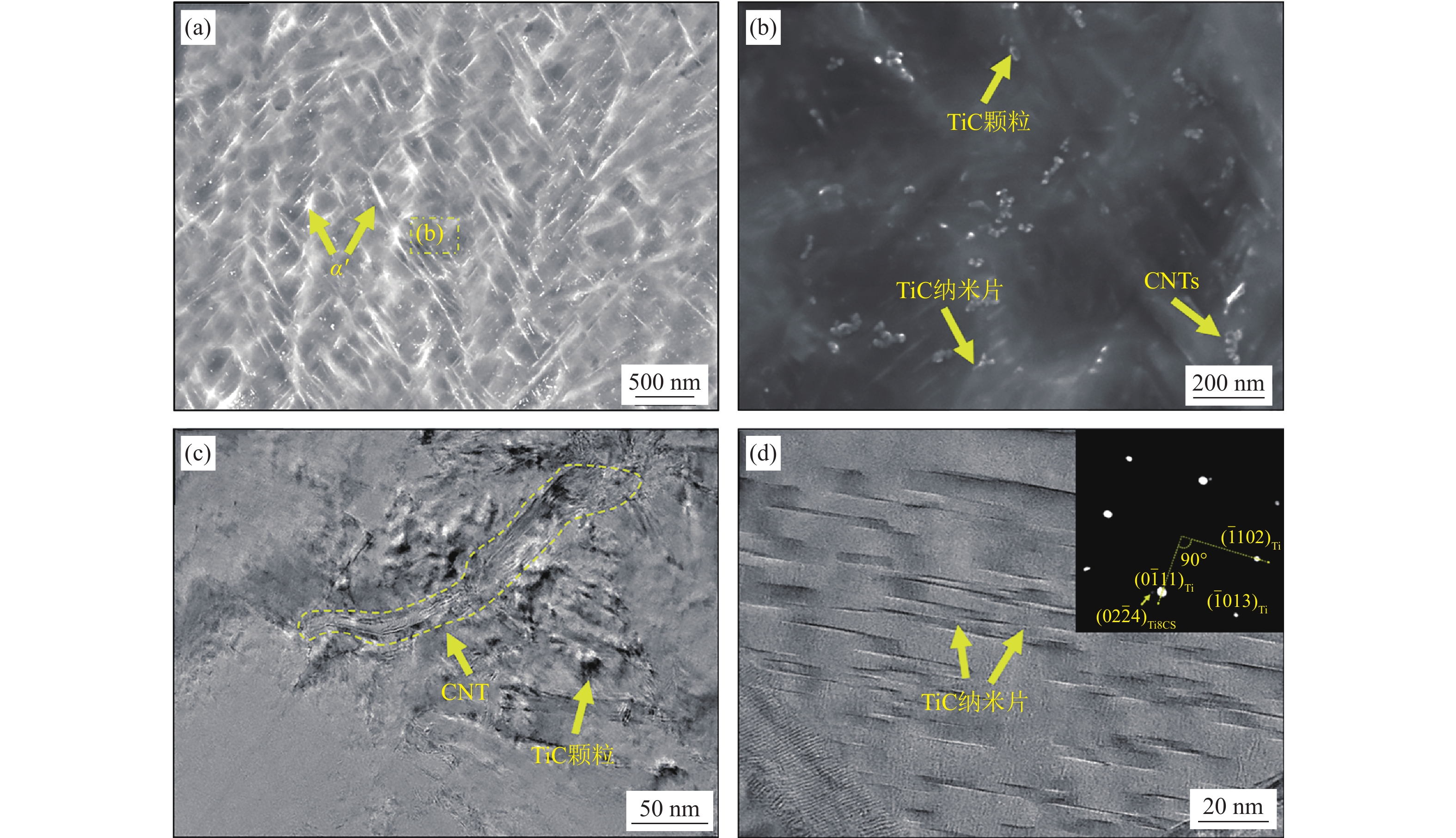
图 3 A‒C/TC4粉的热压烧结组织及增强相[29]:(a)和(b)A–C/TC4粉体的烧结组织和增强相分布的扫描电镜照片;(c)和(d)α-Ti晶内分布纳米片状增强相的形貌及物相分析;(e)和(f)β-Ti晶内分布颗粒增强相的形貌及物相分析
Figure 3. Sintered A–C/TC4 samples and the reinforcements[29]: (a) and (b) SEM images of the sintered A–C/TC4 samples and the reinforcement distribution; (c) and (d) the morphology and phase analysis of the nanoplatelets inside α-Ti grains; (e) and (f) the morphology and phase analysis of the nanoparticles inside β-Ti grains
![]()
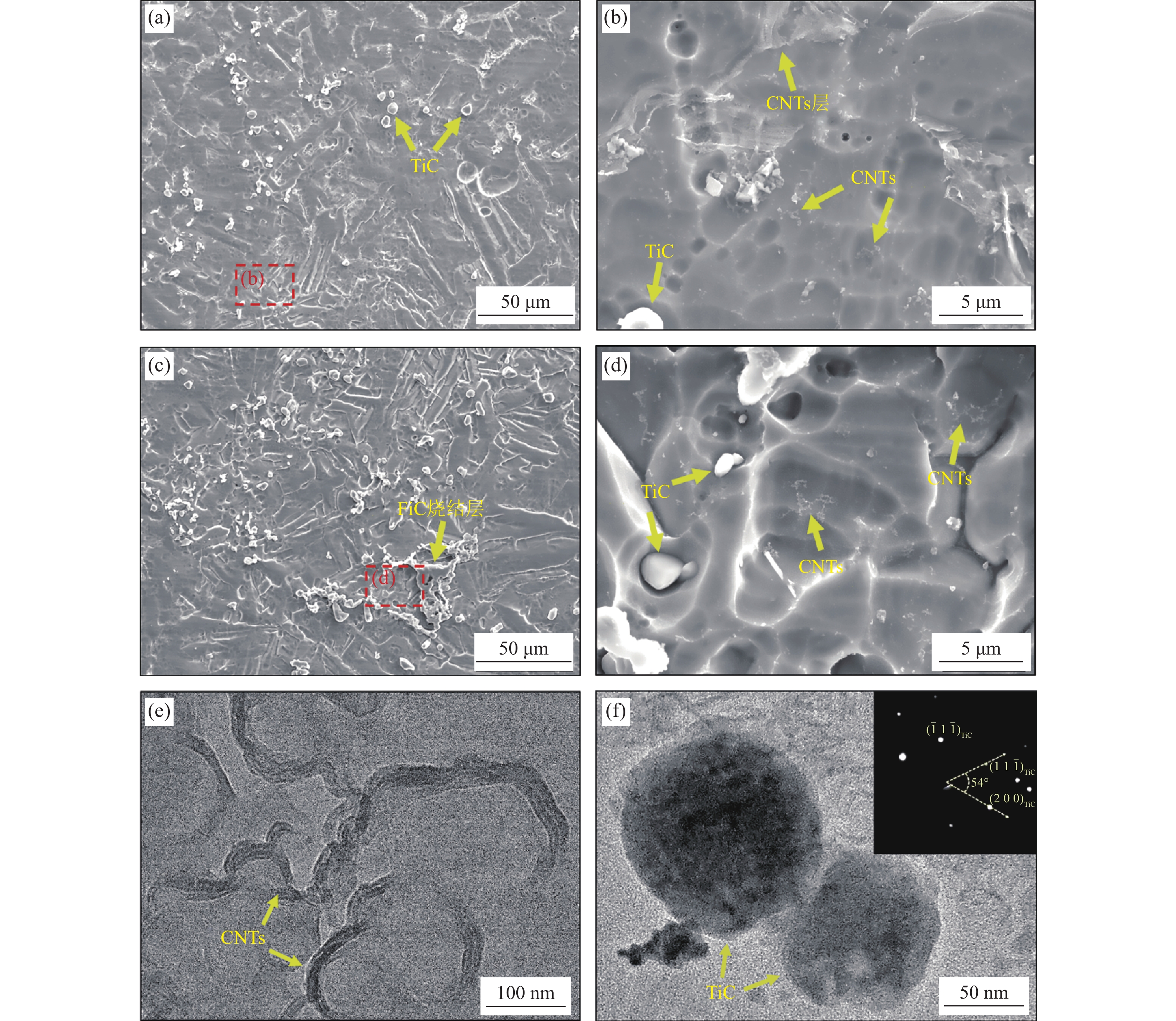
图 4 CNTs/Ti粉在不同温度的烧结组织和增强相形貌分布[31]:(a)和(b)900 ℃;(c)和(d)1000 ℃;(e)和(f)900 ℃烧结样品中保留的CNTs和形成的TiC颗粒
Figure 4. Microstructure of the CNTs/Ti powder samples sintered at different temperatures[31]: (a) and (b) 900 ℃; (c) and (d) 1000 ℃; (e) and (f) TEM images of the remained CNTs and the formed TiC nanoparticles in the CNTs/Ti powder samples sintered at 900 ℃
![]()
![]()
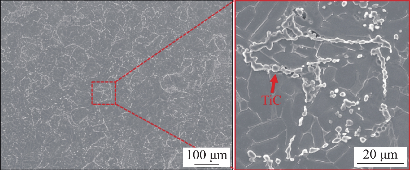
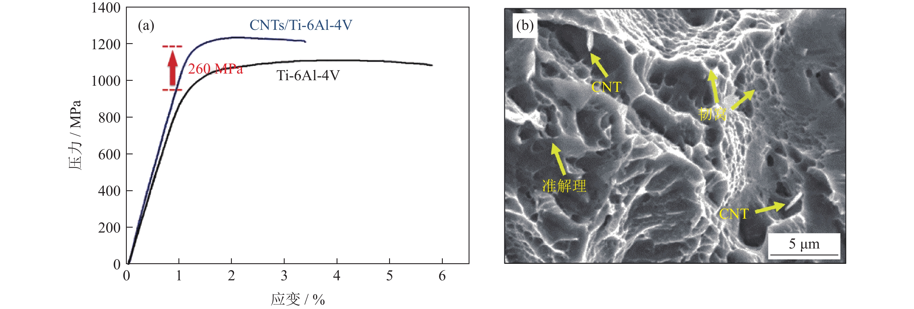
图 6 CNTs/TC4粉体的热压烧结组织
Figure 6. Microstructures of the samples fabricated from the CNTs/TC4 powders by hot press sintering
![]()
图 7 H‒C/TC4粉体烧结组织及增强相[32]:(a)和(b)H–C/TC4粉体烧结组织及增强相分布;(c)~(e)晶界增强相的透射电子显微镜照片;(f)晶内增强相的透射电子显微镜照片
Figure 7. Sintered H–C/TC4 samples and the reinforcements[32]: (a) and (b) sintered H–C/TC4 sample microstructures and the reinforcement distribution; (c)~(e) TEM images of the interfacial reinforcements; (f) TEM images of the intragranular reinforcements
![]()
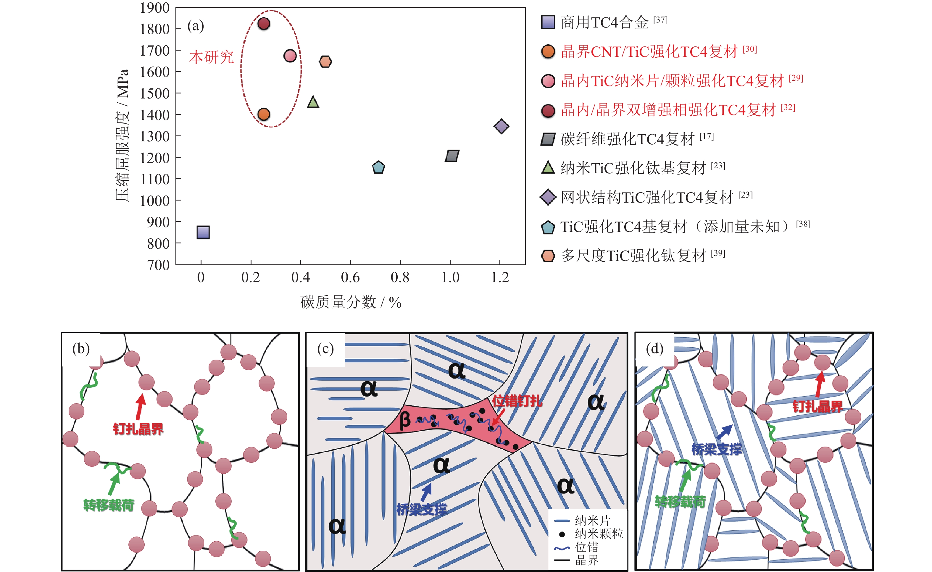
图 8 不同形貌和分布组合增强相强化钛基复合材料[29‒32]:(a)与文献报道中钛基复合材料压缩屈服强度对比;(b)晶界增强相的强化机制;(c)晶内增强相的强化机制;(d)晶内/晶界双增强相组织的强化机制示意图
Figure 8. Reinforcements with the different morphologies and distribution combinations in TMCs[29‒32]: (a) comparison of the TMCs compressive yield strength reported in literatures; (b) strengthening mechanisms of the interfacial reinforcements; (c) strengthening mechanisms of the intragranular reinforcements; (d) strengthening mechanism of the interfacial/intragranular double reinforced phase
![]()
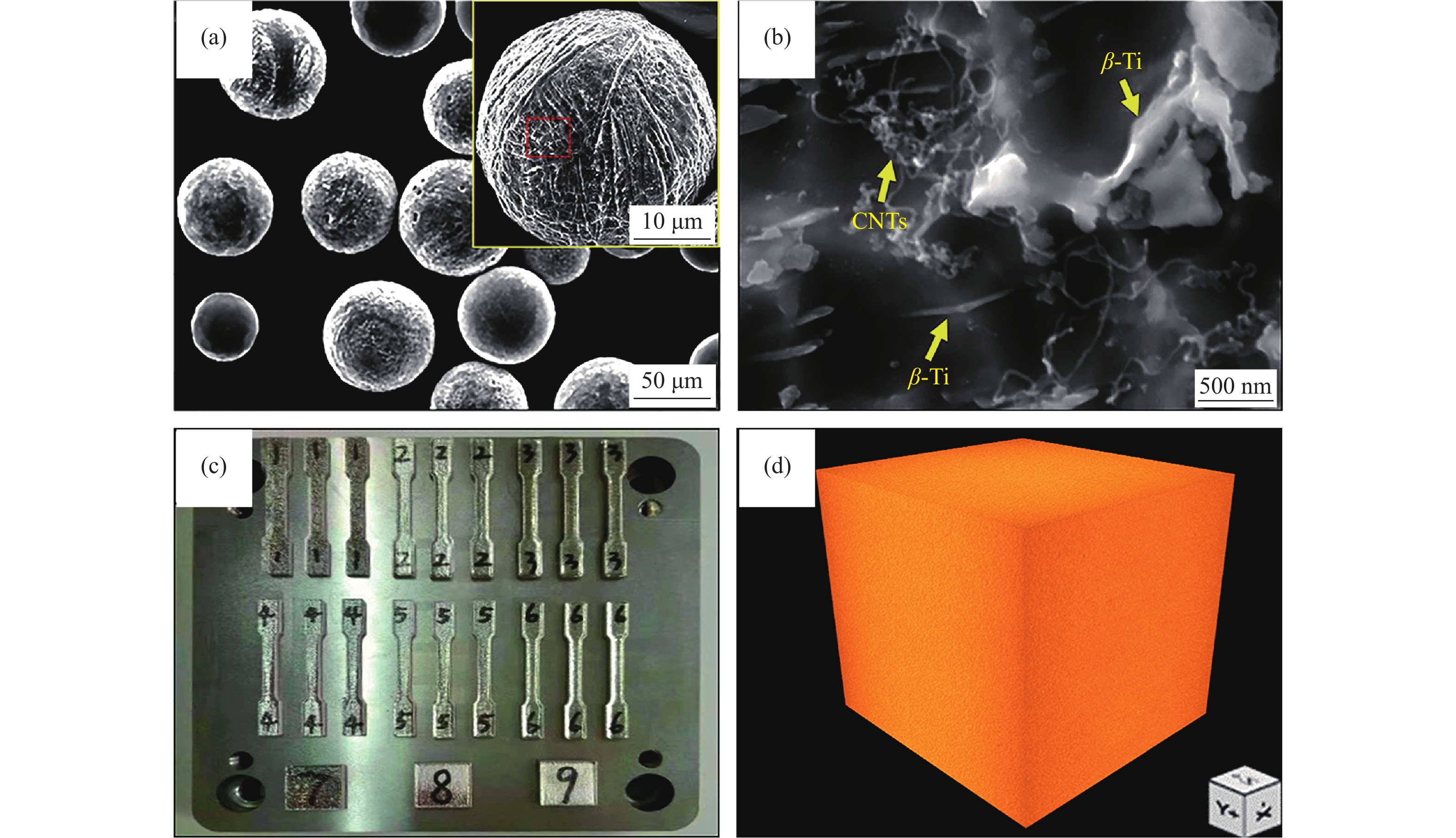
图 9 CNTs/GA–TC4粉体的扫描电镜形貌(a)、原位合成CNTs扫描电镜形貌(b)、复合粉体打印样品宏观形貌(c)及打印样品的三维重构照片(d)[47]
Figure 9. SEM image of the CNTs/GA–TC4 powders (a), SEM image of the in situ synthesized CNTs (b), macro-profile of the samples printed by the CNTs/GA–TC4 powders (c), and 3D reconstructed images of the printed sample (d)[48]
![]()
-
[1] Hayat M D, Singh H, He Z, et al. Titanium metal matrix composites: An overview. Composites Part A, 2019, 121: 418 DOI: 10.1016/j.compositesa.2019.04.005
[2] Huang L J, An Q, Geng L, et al. Multiscale architecture and superior high-temperature performance of discontinuously reinforced titanium matrix composites. Adv Mater, 2021, 33(6): 2000688 DOI: 10.1002/adma.202000688
[3] Jiao Y, Huang L J, Geng L. Progress on discontinuously reinforced titanium matrix composites. J Alloys Compd, 2018, 767: 1196 DOI: 10.1016/j.jallcom.2018.07.100
[4] Huang L J, Geng L, Peng H X. Microstructurally inhomogeneous composites: Is a homogeneous reinforcement distribution optimal? Prog Mater Sci, 2015, 71: 93
[5] Namini A S, Dilawary S A A, Motallebzadeh A, et al. Effect of TiB2 addition on the elevated temperature tribological behavior of spark plasma sintered Ti matrix composite. Composites Part B, 2019, 172: 271 DOI: 10.1016/j.compositesb.2019.05.073
[6] Liao Z R, Abdelhafeez A, Li H N, et al. State-of-the-art of surface integrity in machining of metal matrix composites. Int J Mach Tool Manuf, 2019, 143: 63 DOI: 10.1016/j.ijmachtools.2019.05.006
[7] Froes F H, Eylon D. Powder metallurgy of titanium alloys. Int Mater Rev, 1990, 35(1): 162 DOI: 10.1179/095066090790323984
[8] Ezugwu E O, Wang Z M. Titanium alloys and their machinability–a review. J Mater Process Technol, 1997, 68: 262 DOI: 10.1016/S0924-0136(96)00030-1
[9] Ma F C, Wang T R, Liu P, et al. Mechanical properties and strengthening effects of in situ (TiB+TiC)/Ti-1100 composite at elevated temperatures. Mater Sci Eng A, 2016, 654: 352 DOI: 10.1016/j.msea.2015.12.071
[10] 黄陆军, 耿林. 网状结构钛基复合材料. 北京: 国防工业出版社, 2015 Huang L J, Geng L. Titanium Matrix Composites with Network Microstructure. Beijing: National Defense Industry Press, 2015
[11] Liu Q, Qi F G, Wang Q, et al. The influence of particles size and its distribution on the degree of stress concentration in particulate reinforced metal matrix composites. Mater Sci Eng A, 2018, 731: 351 DOI: 10.1016/j.msea.2018.06.067
[12] Yan Q, Chen B, Cao L, et al. Improved mechanical properties in titanium matrix composites reinforced with quasi-continuously networked graphene nanosheets and in-situ formed carbides. J Mater Sci Technol, 2022, 96: 85 DOI: 10.1016/j.jmst.2021.03.073
[13] 汤慧萍, 黄伯云, 刘咏, 等. 粉末冶金颗粒增强钛基复合材料研究进展. 粉末冶金技术, 2004, 22(5): 293 DOI: 10.3321/j.issn:1001-3784.2004.05.008 Tang H P, Huang B Y, Liu Y, et al. Progress in powder metallurgy particle reinforced Ti matrix composite. Powder Metall Technol, 2004, 22(5): 293 DOI: 10.3321/j.issn:1001-3784.2004.05.008
[14] 杨宇承, 潘宇, 路新, 等. 粉末冶金法制备颗粒增强钛基复合材料的研究进展. 粉末冶金技术, 2020, 38(2): 150 DOI: 10.19591/j.cnki.cn11-1974/tf.2020.02.011 Yang Y C, Pan Y, Lu X, et al. Research progress on particle-reinforced titanium matrix composites prepared by powder metallurgy method. Powder Metall Technol, 2020, 38(2): 150 DOI: 10.19591/j.cnki.cn11-1974/tf.2020.02.011
[15] Saba F, Zhang F M, Liu S L, et al. Tribological properties, thermal conductivity and corrosion resistance of titanium/nanodiamond nanocomposites. Compos Commun, 2018, 10: 57 DOI: 10.1016/j.coco.2018.06.008
[16] Wang F C, Zhang Z H, Sun Y J, et al. Rapid and low temperature spark plasma sintering synthesis of novel carbon nanotube reinforced titanium matrix composites. Carbon, 2015, 95: 396 DOI: 10.1016/j.carbon.2015.08.061
[17] Lü S, Li J S, Li S F, et al. Effects of heat treatment on interfacial characteristics and mechanical properties of titanium matrix composites reinforced with discontinuous carbon fibers. J Alloys Compd, 2021, 877: 160313 DOI: 10.1016/j.jallcom.2021.160313
[18] Munir K S, Zheng Y F, Zhang D L, et al. Improving the strengthening efficiency of carbon nanotubes in titanium metal matrix composites. Mater Sci Eng A, 2017, 696: 10 DOI: 10.1016/j.msea.2017.04.026
[19] Munir K S, Li Y C, Qian M, et al. Identifying and understanding the effect of milling energy on the synthesis of carbon nanotubes reinforced titanium metal matrix composites. Carbon, 2016, 99: 384 DOI: 10.1016/j.carbon.2015.12.041
[20] Munir K S, Li Y C, Li J X, et al. Interdependencies between graphitization of carbon nanotubes and strengthening mechanisms in titanium matrix composites. Materialia, 2018, 3: 122 DOI: 10.1016/j.mtla.2018.08.015
[21] Zhang X, Zhao N Q, He C N. The superior mechanical and physical properties of nanocarbon reinforced bulk composites achieved by architecture design–A review. Prog Mater Sci, 2020, 113: 100672 DOI: 10.1016/j.pmatsci.2020.100672
[22] 冯俊, 姜中涛, 韩骐璘. 不连续增强钛基复合材料的研究进展. 粉末冶金技术, 2020, 38(5): 392 DOI: 10.19591/j.cnki.cn11-1974/tf.2019070001 Feng J, Jiang Z T, Han Q L. Research progress on discontinuous reinforced titanium matrix composites. Powder Metall Technol, 2020, 38(5): 392 DOI: 10.19591/j.cnki.cn11-1974/tf.2019070001
[23] Luo S D, Li Q, Tian J, et al. Self-assembled, aligned TiC nanoplatelet-reinforced titanium composites with outstanding compressive properties. Scr Mater, 2013, 69: 29 DOI: 10.1016/j.scriptamat.2013.03.017
[24] Geng L, Ni D R, Zhang J, et al. Hybrid effect of TiBw and TiCp on tensile properties of in situ titanium matrix composites. J Alloys Compd, 2008, 463(1): 488
[25] Huang L J, Geng L, Xu H Y, et al. In situ TiC particles reinforced Ti6Al4V matrix composite with a network reinforcement architecture. Mater Sci Eng A, 2011, 528: 2859 DOI: 10.1016/j.msea.2010.12.046
[26] Huang L J, Geng L, Peng H X, et al. High temperature tensile properties of in situ TiBw/Ti6Al4V composites with a novel network reinforcement architecture. Mater Sci Eng A, 2012, 534: 688 DOI: 10.1016/j.msea.2011.12.028
[27] Zadra M, Girardini L. High-performance, low-cost titanium metal matrix composites. Mater Sci Eng A, 2014, 608: 155 DOI: 10.1016/j.msea.2014.04.066
[28] 宋杰光, 纪岗昌, 李世斌, 等. 粉体包覆技术的研究进展. 材料导报, 2009, 23(增刊1): 164 Song J G, Ji G C, Li S B, et al. Review on coating technology of powder. Mater Rev, 2009, 23(Suppl 1): 164
[29] Li S F, Tan C, Liu Y, et al. Designing core-shell C-coated Ti–6Al–4V powders for high-performance nano-sized TiC platelets/particles synergistically reinforced Ti–6Al–4V composites. Materialia, 2018, 2: 68 DOI: 10.1016/j.mtla.2018.06.010
[30] Li S F, Liu Y, Yang Y F. Activating trace Fe impurity as catalyst to plant carbon nanotubes within Ti–6Al–4V powders for high-performance Ti-matrix composites. Metall Mater Trans A, 2019, 50: 3975 DOI: 10.1007/s11661-019-05321-x
[31] Li S F, Cui J Y, Yang Y F, et al. In situ growth of carbon nanotubes on Ti powder for strengthening of Ti matrix composite via nanotube-particle dual morphology. Metall Mater Trans A, 2020, 51: 5932 DOI: 10.1007/s11661-020-05988-7
[32] Li S F, Yang Y F, Misra R D K, et al. Interfacial/intragranular reinforcement of titanium-matrix composites produced by a novel process involving core-shell structured powder. Carbon, 2020, 164: 378 DOI: 10.1016/j.carbon.2020.04.010
[33] Li S F, Geng K, Misra R D K, et al. Commercial scale uniform powder coating for metal additive manufacturing. JOM, 2020, 72: 4639 DOI: 10.1007/s11837-020-04386-z
[34] Vasanthakumar K, Karthiselva N S, Chawake N M, et al. Formation of TiCx during reactive spark plasma sintering of mechanically milled Ti/carbon nanotube mixtures. J Alloys Compd, 2017, 709: 829 DOI: 10.1016/j.jallcom.2017.03.216
[35] Adegbenjoa A O, Olubambia P A, Potgieter J H, et al. Spark plasma sintering of graphitized multi-walled carbon nanotube reinforced Ti6Al4V. Mater Des, 2017, 128: 119 DOI: 10.1016/j.matdes.2017.05.003
[36] Munir K S, Oldfield D T, Wen C. Role of process control agent in the synthesis of multi-walled carbon nanotubes reinforced titanium metal matrix powder mixtures. Adv Eng Mater, 2016, 18: 294 DOI: 10.1002/adem.201500346
[37] Lee H J, Kim S H, Lee J C. Promotion of C diffusion to prepare a high-strength wear-resistant Ti alloy. Scr Mater, 2016, 115: 33 DOI: 10.1016/j.scriptamat.2015.12.024
[38] Hao Y J, Liu J X, Li J H, et al. Rapid preparation of TiC reinforced Ti6Al4V based composites by carburizing method through spark plasma sintering technique. Mater Des, 2015, 65: 94 DOI: 10.1016/j.matdes.2014.09.008
[39] Zhang X J, Song F, Wei Z P, et al. Microstructural and mechanical characterization of in-situ TiC/Ti titanium matrix composites fabricated by graphene/Ti sintering reaction. Mater Sci Eng A, 2017, 705: 153 DOI: 10.1016/j.msea.2017.08.079
[40] Zhang D Y, Qiu D, Gibson M A, et al. Additive manufacturing of ultrafine-grained high-strength titanium alloys. Nature, 2019, 576: 91 DOI: 10.1038/s41586-019-1783-1
[41] Yu W H, Sing S L, Chua C K, et al. Particle-reinforced metal matrix nanocomposites fabricated by selective laser melting: A state of the art review. Prog Mater Sci, 2019, 104: 330 DOI: 10.1016/j.pmatsci.2019.04.006
[42] Yan Q, Chen B, Li J S. Super-high-strength graphene/titanium composites fabricated by selective laser melting. Carbon, 2021, 174: 451 DOI: 10.1016/j.carbon.2020.12.047
[43] Zeng X, Yamaguchi T, Nishio K. Characteristics of Ti(C, N)/TiB composite layer on Ti–6Al–4V alloy produced by laser surface melting. Opt Laser Technol, 2016, 80: 84 DOI: 10.1016/j.optlastec.2016.01.004
[44] Gu D D, Hagedorn Y C, Meiners W, et al. Selective laser melting of in-situ TiC/Ti5Si3 composites with novel reinforcement architecture and elevated performance. Surf Coat Technol, 2011, 205: 3285 DOI: 10.1016/j.surfcoat.2010.11.051
[45] Gu D D, Meng G B, Li C, et al. Selective laser melting of TiC/Ti bulk nanocomposites: Influence of nanoscale reinforcement. Scr Mater, 2012, 67: 185 DOI: 10.1016/j.scriptamat.2012.04.013
[46] He B B, Chang K, Wu W H, et al. The formation mechanism of TiC reinforcement and improved tensile strength in additive manufactured Ti matrix nanocomposite. Vacuum, 2017, 143: 23 DOI: 10.1016/j.vacuum.2017.05.029
[47] Liu Y, Li S F, Misra R D K, et al. Planting carbon nanotubes within Ti–6Al–4V to make high-quality composite powders for 3D printing high-performance Ti–6Al–4V matrix composites. Scr Mater, 2020, 183: 6 DOI: 10.1016/j.scriptamat.2020.03.009
[48] Gu D D, Rao X W, Dai D H, et al. Laser additive manufacturing of carbon nanotubes (CNTs) reinforced aluminum matrix nanocomposites: Processing optimization, microstructure evolution and mechanical properties. Addit Manuf, 2019, 29: 100801
[49] Aboulkhair N T, Simonelli M, Salama E, et al. Evolution of carbon nanotubes and their metallurgical reactions in Al-based composites in response to laser irradiation during selective laser melting. Mater Sci Eng A, 2019, 765: 138307 DOI: 10.1016/j.msea.2019.138307
[50] Zhang B C, Bi G J, Chew Y X, et al. Comparison of carbon-based reinforcement on laser aided additive manufacturing Inconel 625 composites. Appl Surf Sci, 2019, 490: 522 DOI: 10.1016/j.apsusc.2019.06.008
-
期刊类型引用(2)
1. 班伟,陈嘉琪,刘璐璐,葛涛,张帅. 紧耦合气雾化喷嘴流场特性研究. 粉末冶金技术. 2024(03): 312-319 .  本站查看
本站查看
2. 朱本章,朱协彬,汪国成,卢燕,姚廷鑫. 真空气雾化法制备纯铜粉末工艺及性能研究. 安徽工程大学学报. 2024(04): 52-58 . 百度学术
其他类型引用(0)

 下载:
下载:


计量
- 文章访问数: 4496
- HTML全文浏览量: 186
- PDF下载量: 77
- 被引次数: 2
