
-
摘要: 从压制阴模模具材料、热处理制度、金相组织等方面研究了粉末冶金压制阴模键子处裂纹形成原因,讨论了粉末冶金齿毂模结构及压制模具设计结构的合理性,通过分析数据得到了开裂的原因并加以改正。结果表明,压制阴模本身的材质选择和热处理制度没有问题,导致裂纹产生的主要原因是整体模具结构设计不合理,导致压制阴模键子损坏。改进原有模具结构可以提高压制模具寿命,降低模具使用成本,保证生产顺利进行。Abstract: The formation of cracks in pressing female dies by powder metallurgy were investigated by die materials, heat treatment process, and metallurgical structures, the structure of gear hub die by powder metallurgy and the design reasonability of pressing dies were discussed, and the crack formation reasons were analyzed and corrected through the detailed data of pressing female dies in this paper. In the results, the material selection and heat treatment process have no connection with the crack formation, the inappropriate design of die structure is the primary reason for the crack formation. Improving the pressing female die structure of gear hub could increase the service life of die, reduce the cost of die, and keep the production running smoothly.
-
Key words:
- powder metallurgy /
- pressing female dies /
- cracks /
- microstructures /
- die life
-

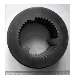
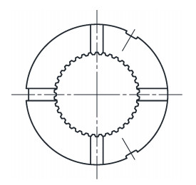
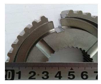
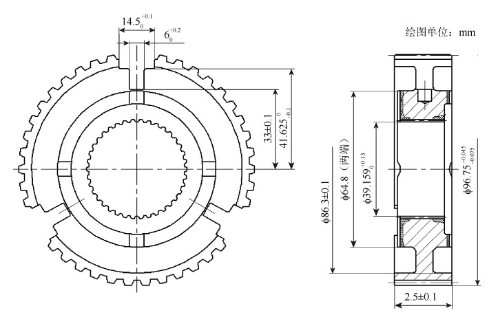
图 1 粉末冶金同步器齿毂产品示意图
Figure 1. Schematic diagram of gear hub synchronizer by powder metallurgy

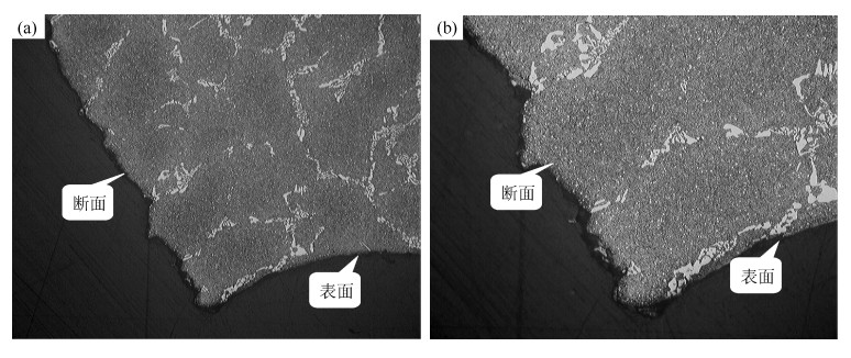
图 5 送检模具样品断口处金相组织形貌:(a)×100;(b)×200
Figure 5. Metallographic structure of fracture in pressing female die sample: (a) ×100; (b) ×200

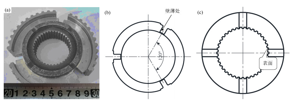
图 6 粉末冶金齿毂产品模具结构:(a)模具宏观结构;(b)二冲俯视图;(c)三冲俯视图
Figure 6. Die structure of gear hub by powder metallurgy: (a) die macrostructure; (b) vertical view after the second impact; (c) vertical view after the third impact

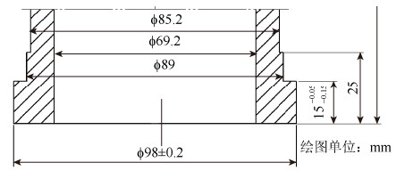
图 7 压制模具二冲底座结构
Figure 7. Understructure of pressing female die sample after the second impact

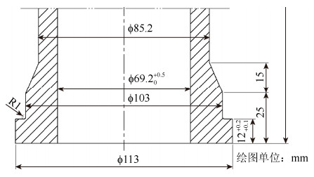
图 8 改进后压制模具上、下二冲底座结构
Figure 8. Improved understructure of pressing female die sample after the second impact

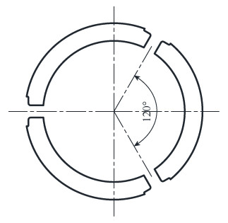
图 9 改进后整体模具压制上、下二冲俯视图
Figure 9. Vertical view of the improved pressing female die sample after the second impact

图 10 改进后整体模具压制上、下三冲俯视图
Figure 10. Vertical view of the improved pressing female die sample after the third impact

图 11 改进后粉末冶金齿毂压制阴模整体模具结构
Figure 11. Improved pressing female die structure of gear hub by powder metallurgy
表 1 模具材料化学成分(质量分数)
Table 1. Chemical composition of die material
% C Si Mn P S Cr V Mo 1.51 0.18 0.28 0.01 0.002 11.11 0.67 0.70  下载: 导出CSV
-
[1] Han F L, Ma F K, Cao Y J. Handbook of Powder Metallurgy Technology. Beijing: Chemical Industry Press, 2007韩凤麟, 马福康, 曹勇家. 粉末冶金技术手册. 北京: 化学工业出版社, 2007 [2] Han F L. China Die and Mould Engineering Canon, Volume 6 — Mould Design of Powder Metallurgy Parts. Beijing: Publishing House of Electronics Industry, 2009韩凤麟. 中国模具工程大典第6卷—粉末冶金零件模具设计. 北京: 电子工业出版社, 2009 [3] Zhang H C. Practical Technology of Powder Metallurgy. Beijing: Metallurgical Industry Press, 2004张华诚. 粉末冶金实用工艺学. 北京: 冶金工业出版社, 2004 [4] Yin H Y, Zhang H C. Design Manual of Powder Metallurgy Mould. 2nd Ed. Beijing: China Machine Press, 2002印红羽, 张华诚. 粉末冶金模具设计手册. 2版. 北京: 机械工业出版社, 2002 [5] Zhou Z P, Shen X P. Practical Technology of Powder Metallurgy Machinery Parts. Beijing: Chemical Industry Press, 2006周作平, 申小平. 粉末冶金机械零件实用技术. 北京: 化学工业出版社, 2006 [6] Shen X P. Manufacturing Engineering of Powder Metallurgy. Beijing: National Defense Industry Press, 2015申小平. 粉末冶金制造工程. 北京: 国防工业出版社, 2015 -

 点击查看大图
计量
- 文章访问数: 227
- HTML全文浏览量: 80
- PDF下载量: 25
- 被引次数: 0
