
Microstructure and electrochemical properties of 3D flower-like CoS anode materials used for lithium ion batteries synthesized by one-step hydrothermal method
-
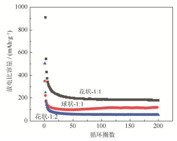
摘要: 以CoCl2·6H2O和硫脲(CH4N2S)为原料, 采用一步水热法, 通过改变钴硫摩尔比和添加表面活性剂制备出两种不同形貌(3D花状和球状)的硫化钴(CoS)锂离子电池负极材料。结果表明, 当钴硫摩尔比为1:1时, 在180℃下水热反应12 h可得到3D花状CoS负极材料, 其三维立体花状结构由纳米级层片组成; 当钴硫摩尔配比为1:1, 添加十六烷基三甲基溴化铵(CTAB), 在180℃下反应12 h可制得由小颗粒聚结成的球状CoS负极材料。在0.1C电流密度下, 3D花状CoS电池首次放电比容量为752 mAh·g-1, 并且具有良好的倍率性能; 在1C电流密度下, 经过200圈的循环测试后, 3D花状CoS电池仍有较高的放电比容量(185 mAh·g-1), 远高于球状CoS电池(118.6 mAh·g -1), 并且没有衰减的趋势。Abstract: Using CoCl2·6H2O and thiourea (CH4N2S) as the raw materials, the 3D flower-like and spherical cobalt sulfide (CoS) anode materials used for lithium ion batteries were synthesized by one-step hydrothermal method in this paper, through changing the molar ratio of Co to S and adding the surfactant. In the results, when the molar ratio of Co to S is 1:1 and the hydrothermal reaction is carried out at 180 fo℃ r 12 h, the obtained 3D flower-like CoS anode materials are composed of nano-scale layer structures. By adding the cetyl trimethyl ammonium bromide (CTAB) as surfactant, the globular cobalt sulfide anode materials formed by the agglomeration of small particles are obtained by hydrothermal reaction at 180 for 12 h℃ when the molar ratio of Co to S is 1:1. The first discharge capacity of 3D flower-like CoS anode materials is 752 mAh·g-1 at 0.1C, showing the good rate capability, and there is still high discharge capacity (185 mAh·g-1) after 200 cycles at 1C without the tendency of decay, which is much higher than that of the spherical CoS anode materials (118.6 mAh·g-1).
-
金属钛因比强度高、无磁性、生物相容性良好等特点,广泛地应用于航空、航天、生物、医疗等领域。在20世纪50年代,人们开始采用真空电弧炉熔炼和铸造的方法生产钛金属,但是熔炼铸造法对材料的利用率不高,导致钛的生产成本很高。同时,钛合金零件在制备过程中极易受到杂质污染,尤其是氧氮污染,导致冶炼、锻造制备钛合金零件困难,更增加了钛及钛合金的加工成本。粉末冶金成形技术基本不需要后续机加工,材料利用率可达90%,可在加工过程中缩短加工步骤、降低加工成本[1-3]。近年来有学者用粉末冶金技术制备了钛及钛合金产品并对其性能进行研究。何杰等[4]利用高速压制工艺成形纯钛生坯,再经1200 ℃真空烧结2.5 h后,获得了密度为4.50 g·cm-3,相对密度为99.8%,硬度为HV 298的纯钛试样。翁启钢等[5]以纯钛粉为原料,在压强20 MPa、温度为600~875 ℃条件下,进行放电等离子烧结(spark plasma sintering,SPS),结果表明,随温度升高,样品的维氏硬度增加,且温度越高增加速率越快,样品的力学性能提高。
微波烧结(microwave sintering,MS)利用具有特殊波段的微波与材料的基本细微结构耦合而产生热量,材料在电磁场中的介电损耗使材料整体加热至烧结温度而实现致密化[6-8]。微波烧结可以避免传统烧结(conventional sintering,CS)为了提高相对密度而增加烧结温度、延长保温时间导致晶粒长大的弊端,同时具有高速、节能、无污染的优点[9-12],在近些年来受到研究者的广泛关注。吴丹等[13]研究了微波烧结对金属粉体的影响。黄加伍和彭虎[14]研究了粉末冶金铁基机械零件在氩气或氮气保护下,在温度1150~1220 ℃、保温5~20 min工艺条件下的微波烧结,并对微波烧结与传统烧结工艺进行对比分析。朱凤霞等[15]研究了纯铜压坯的微波烧结,在功率为1 kW、频率为2.45 GHz的微波炉中对纯铜压坯进行烧结,结果表明微波烧结可以在短时间内使纯铜压坯致密化,相对密度达97.3%。本文通过传统烧结与微波烧结制备纯钛试样,探讨不同烧结工艺对粉末烧结钛的组织及力学性能的影响。
1. 实验材料及方法
实验所用原料为平均粒径是36 μm的氢化脱氢纯钛粉,其形貌如图 1所示,由图可知纯钛粉为不规则状粉末,呈银灰色。纯钛粉化学成分如表 1所示。
表 1 纯Ti粉化学成分(质量分数)Table 1. Chemical composition of pure Ti powders% Fe Si Mg Mn O C N H Ti 其他 0.06 0.02 0.02 0.02 0.30 0.02 0.05 0.04 余量 0.05 在500 MPa、30 s保压时间的压制条件下,将钛粉与添加剂的混合粉末压成尺寸为ϕ11 mm × 15 mm的压坯。使用GSL1700X真空管式炉,在氩气气氛下将压坯加热到1200 ℃,保温2 h进行传统烧结,随后炉冷至室温,得到传统烧结试样。使用MKZ-M2B型微波烧结炉(功率1600 W,微波频率2450±50 MHz),在氩气气氛下将压坯加热到1200 ℃,保温15 min进行微波烧结,随后水冷至室温,得到微波烧结试样。
使用XRD-7000X射线衍射仪对原料粉末及烧结试样的物相进行检测,扫描范围2θ为30°~80°,扫描速度为8°/min;使用OLYMPUS-GX71型金相显微镜对不同烧结方式制得的样品进行金相组织观察和孔隙分布统计,用体积比为HF: HNO3: H2O = 2:4:94的混合酸进行腐蚀,腐蚀时间约10 s;采用阿基米德排水法,使用ESJ200-4型电子分析天平(精度为0.1 mg)测量试样的密度;使用HV-120维氏硬度计对不同烧结方式得到的试样进行显微硬度测量,测量载荷为HV 10,保荷时间为10 s;使用HT-2402万能试验机对样品进行压缩性能测试;使用JSM-6700E扫描电子显微镜观察烧结纯钛的断口形貌。
2. 结果与讨论
2.1 显微组织结构观察与分析
图 2是纯钛粉、传统烧结与微波烧结纯钛试样的X射线衍射(X-ray diffraction,XRD)图,从曲线(a)、(b)可以看出,传统烧结纯钛试样与钛粉原料的衍射峰相似,只有α-Ti的特征峰,但后者比前者的衍射峰更高,晶化比较明显,说明传统烧结产物为α-Ti。从曲线(c)可以看出微波烧结纯钛试样既出现α-Ti的衍射峰还出现了β-Ti的衍射峰,说明微波烧结的产物既有α-Ti也有β-Ti。钛具有α-Ti与β-Ti两种同素异构体,在890 ℃左右纯钛开始由α-Ti向β-Ti转变,在905 ℃左右α-Ti将完全转变为高温相β-Ti[16-18]。本文实验中传统烧结与微波烧结的温度均为1200 ℃,在升温后保温阶段烧结Ti完全转变为高温β-Ti。在冷却过程中,一方面由于微波烧结的冷却方式为通水冷却,冷却速度快;另一方面,微波烧结的加热方式是由内及外的,内外存在一定的温度梯度,温度可以快速降到890 ℃同素异构相转变温度点以下,Ti原子没有足够时间扩散重组,β-Ti不能完全转变为α-Ti,有少量β-Ti残留,所以微波烧结纯钛试样既有α-Ti又有β-Ti。传统烧结的冷却方式为随炉冷却,降温速度慢,降温过程中β-Ti有足够时间扩散转变为α-Ti,所以传统烧结纯钛试样只有α-Ti。
![]() 图 2 不同烧结方式制备的纯钛试样X射线衍射图谱:(a)纯钛粉;(b)传统烧结;(c)微波烧结Figure 2. XRD spectrum of pure titanium samples by different sintering technology: (a) pure Ti powders; (b) conventional sintering; (c) microwave sintering
图 2 不同烧结方式制备的纯钛试样X射线衍射图谱:(a)纯钛粉;(b)传统烧结;(c)微波烧结Figure 2. XRD spectrum of pure titanium samples by different sintering technology: (a) pure Ti powders; (b) conventional sintering; (c) microwave sintering图 3是传统烧结与微波烧结纯钛试样金相组织照片。由图 3(a)和图 3(b)可以看出,不管是传统烧结还是微波烧结,腐蚀前的纯钛试样除了有一定的孔隙(见图中的黑点),两者的组织基本一样。图 3(c)和图 3(d)则表现出明显的不同,腐蚀后的传统烧结纯钛试样基本为等轴晶,没有其他相;腐蚀后的微波烧结纯钛试样除了等轴状的组织外,还有一些黑色条状的组织,呈不连续网篮分布。
![]() 图 3 1200 ℃传统烧结与微波烧结纯钛试样金相组织:(a)传统烧结腐蚀前;(b)微波烧结腐蚀前;(c)传统烧结腐蚀后;(d)微波烧结腐蚀后Figure 3. Microstructures of pure titanium samples by different sintering technology at 1200 ℃ (a) conventional sintering before corrosion; (b) microwave sintering before corrosion; (c) conventional sintering after corrosion; (d) microwave sintering after corrosion
图 3 1200 ℃传统烧结与微波烧结纯钛试样金相组织:(a)传统烧结腐蚀前;(b)微波烧结腐蚀前;(c)传统烧结腐蚀后;(d)微波烧结腐蚀后Figure 3. Microstructures of pure titanium samples by different sintering technology at 1200 ℃ (a) conventional sintering before corrosion; (b) microwave sintering before corrosion; (c) conventional sintering after corrosion; (d) microwave sintering after corrosion由图 3(a)和图 3(b)可以看出,腐蚀前微波烧结与传统烧结纯钛试样相对密度较好,无裂纹、异常孔隙等缺陷,但相对于传统烧结试样,微波烧结试样孔隙度略大,相对密度略差。这是由于传统烧结保温时间长,烧结的三个阶段得以充分进行,压坯在加热过程中有足够的时间扩散传质,使孔隙由大变小,小气孔被大气孔合并,大气孔变成封闭的小气孔,封闭孔隙球化和缩小,所以传统烧结试样孔隙数量较少,且孔隙较小,相对密度较微波烧结试样大。图 3(c)和图 3(d)可以看出,腐蚀后传统烧结纯钛试样晶粒较大,基本为等轴晶,微波烧结纯钛试样晶粒尺寸较小。这是由于传统烧结保温时间长,有充分的扩散与传质使晶粒长大,所以传统烧结纯钛试样的晶粒尺寸大于微波烧结的晶粒尺寸。此外,微波烧结除了有与传统烧结纯钛相似的组织外,还有明显的黑色条纹组织,呈不连续网篮分布。本实验原料为纯度高达99.4%的钛粉,实验过程中无其他杂质元素来源,所以图 3(d)中黑色条纹状组织为不同于基体的纯钛第二相,结合上述X射线衍射分析可以认为传统烧结纯钛为等轴状α-Ti,微波烧结纯钛为等轴状α-Ti与条状β-Ti。
2.2 性能测试结果与分析
表 2是传统烧结与微波烧结制备的纯钛相对密度,可以看出传统烧结与微波烧结纯钛试样的相对密度明显高于生坯,说明无论是保温2 h的传统烧结,还是保温15 min的微波烧结,生坯都得以致密化。由表 2还可以看出,传统烧结纯钛的相对密度略高于微波烧结纯钛,但微波烧结方法较传统烧结方法能有效节约烧结时间。这是因为两种烧结方式的加热机制不同,传统烧结的传热机制是由外向内辐射,为了保证样品内部温度均匀、温差小,防止样品内部出现裂纹,升温速度慢,保温时间长,所以传统烧结时间长。微波烧结是由微波与坯体中的每个颗粒表面耦合使颗粒表面的粒子震动进行整体加热[19],样品内部不存在温差,升温速度快,保温时间短,所以微波烧结可以在较短的时间内有效致密化。由于传统烧结的保温时间大于微波烧结的保温时间,原子有充分的时间扩散传质使气孔排除,烧结样品的相对密度增加,导致传统烧结纯钛相对密度高于微波烧结纯钛,这与前面看到的金相组织基本一致。同时在微波烧结过程中,压坯的孔隙间可能产生火花放电[19],压坯密度低的地方有更多的能量使坯体得以致密化,所以微波烧结样品的相对密度与原始坯体的密度关系较小。
表 2 不同烧结方式制备纯钛的相对密度Table 2. Relative density of pure titanium samples by different sintering technology试样编号 相对密度/% 密度/(g·cm-3) 生坯 75.00 3.3825 微波烧结(1200 ℃,15 min) 95.45 4.3048 传统烧结(1200 ℃,2 h) 96.06 4.3323 图 4是传统烧结与微波烧结纯钛沿不同方向上的硬度分布,图 4(a)是垂直于压制方面靠近压头端由中心到周围的硬度分布,图 4(b)是沿压制方向从压头到底面处的硬度分布。从图中可以看出,不论是那个方向,微波烧结纯钛的硬度均大于传统烧结纯钛,微波烧结纯钛的平均硬度为HV 311,传统烧结纯钛的平均硬度为HV 260;另外,从图 4(a)还可以看出,微波烧结纯钛从中间到两边有一个微小的硬度梯度,表现为中心处的硬度略高于其边缘处硬度,而传统烧结纯钛的硬度在有限的范围内,中心与边缘处基本无差异。分析其原因,一是由于微波烧结制得样品的晶粒尺寸小,且存在β-Ti第二相,在细晶强化和第二相强化的作用下,微波烧结纯钛的硬度大于传统烧结纯钛;二是由于传统烧结的加热方式为热传递,且保温时间较长,故样品内部各部分温度差不大,中心与边缘处硬度基本无差异,微波烧结的加热方式为体加热,即材料对微波能量吸收均匀,但由于材料外部与气氛直接接触,导致内部温度略高于外部温度,所以中心处的硬度高于其边缘处硬度。从图 4(b)可以看出,传统烧结与微波烧结纯钛的硬度从压头端到底面处的硬度逐渐减小,两者变化趋势基本一致,这是由于粉末与模壁之间的外摩擦力随着远离压头逐渐增大的缘故,这与经典粉末单向压制得到的压坯密度分布规律是一致的。
![]() 图 4 传统烧结与微波烧结纯钛试样硬度分布:(a)垂直于压制方向,靠近压头端由中心到周围的硬度分布;(b)沿压制方向,从压头到底面处的硬度分布Figure 4. Vickers hardness distribution of pure titanium samples by conventional sintering and microwave sintering: (a) perpendicular to the pressing direction from the center to around; (b) along the pressing direction from the pressure head to bottom
图 4 传统烧结与微波烧结纯钛试样硬度分布:(a)垂直于压制方向,靠近压头端由中心到周围的硬度分布;(b)沿压制方向,从压头到底面处的硬度分布Figure 4. Vickers hardness distribution of pure titanium samples by conventional sintering and microwave sintering: (a) perpendicular to the pressing direction from the center to around; (b) along the pressing direction from the pressure head to bottom图 5是微波烧结与传统烧结纯钛试样的压缩应力-应变曲线。从图可以看出,两种烧结钛均有明显的弹性变形和塑性变形,而微波烧结试样的弹性模量(曲线斜率)略大于传统烧结试样,这与前面的硬度分析是一致的,而传统烧结试样的压断强度则要高于微波烧结试样,这可能与其相对密度较大有关。经计算,传统烧结与微波烧结纯钛试样的抗压强度分别为1309 MPa和1175 MPa,断面膨胀率分别为10.63%和18.89%。另外,从图中可以看出,微波烧结试样有明显的塑性变形,传统烧结试样塑性变形不明显,微波烧结试样相对于传统烧结试样表现出一定的塑性,这是因为微波烧结纯钛是由密排六方晶型的α-Ti基体与体心立方晶型的β-Ti组成,传统烧结纯钛全部由密排六方的α-Ti组成,而体心立方较密排六方有更多的滑移系,使其表现出一定的塑性;再者,微波烧结纯钛的孔隙率大于传统烧结纯钛的孔隙率,而较多的空隙也起到一定的增韧作用。
![]() 图 5 传统烧结与微波烧结纯钛试样的压缩应力-应变曲线Figure 5. Compression stress-strain curves of pure titanium samples by conventional sintering and microwave sintering
图 5 传统烧结与微波烧结纯钛试样的压缩应力-应变曲线Figure 5. Compression stress-strain curves of pure titanium samples by conventional sintering and microwave sintering图 6是不同烧结工艺制备的纯钛试样断口形貌,从图中可以看出,传统烧结纯钛与微波烧结纯钛均为脆性断裂,传统烧结纯钛的断口形貌有明显的解理面,即“河流花样”,为典型的脆性断裂形貌;微波烧结纯钛的压缩断口由平坦的“类解理”小平面、微孔及撕裂棱组成的混合断裂,属于准解理的脆性断裂[20]。表明传统烧结纯钛的脆性大于微波烧结纯钛的脆性,这与压缩实验的结果相吻合。
![]() 图 6 传统烧结与微波烧结纯钛试样断口形貌:(a)传统烧结(×60);(b)传统烧结(×2000);(c)传统烧结(×5000);(d)微波烧结(×40);(e)微波烧结(×2000);(f)微波烧结(×5000)Figure 6. Fracture morphology of pure titanium samples by different sintering technology: (a) conventional sintering (×60); (b) conventional sintering (×2000); (c) conventional sintering (×5000); (d) microwave sintering (×40); (e) microwave sintering (×2000); (f) microwave sintering (×5000)
图 6 传统烧结与微波烧结纯钛试样断口形貌:(a)传统烧结(×60);(b)传统烧结(×2000);(c)传统烧结(×5000);(d)微波烧结(×40);(e)微波烧结(×2000);(f)微波烧结(×5000)Figure 6. Fracture morphology of pure titanium samples by different sintering technology: (a) conventional sintering (×60); (b) conventional sintering (×2000); (c) conventional sintering (×5000); (d) microwave sintering (×40); (e) microwave sintering (×2000); (f) microwave sintering (×5000)3. 结论
(1)平均粒径36 μm的纯钛粉经500 MPa冷压成型,在1200 ℃经传统烧结保温2 h得到等轴α-Ti,密度为4.3323 g·cm-3,相对密度为96.06%,硬度为HV 260,抗压强度为1309 MPa,断面膨胀率为10.63%,断裂呈典型的解理脆性断裂。
(2)平均粒径36 μm的纯钛粉经500 MPa冷压成型,在1200 ℃经微波烧结保温15 min得到较细小的等轴α-Ti与少量条状β-Ti,密度为4.3048 g·cm-3,相对密度为95.45%,硬度为HV 311,抗压强度为1175 MPa,断面膨胀率为18.89%,表现出一定的塑性,呈准解理状脆性断裂。
-
![]()
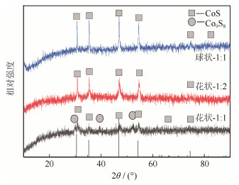
图 1 花状和球状硫化钴试样X射线衍射图谱
Figure 1. XRD spectra of flower-like and spherical cobalt sulfide samples
![]()
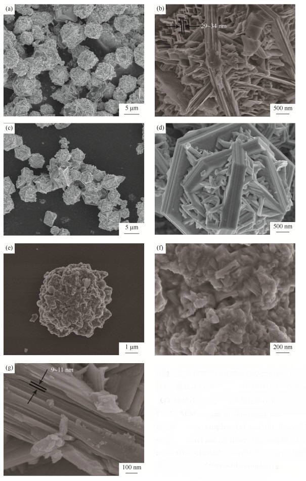
图 2 花状和球状硫化钴试样显微形貌:(a)和(b)花状-1:1;(c)和(d)花状-1:2;(e)和(f)球状-1:1;(g)高倍率花状-1:1
Figure 2. SEM images of flower-like and spherical cobalt sulfide samples: (a) and (b) flower-like sample-1:1; (c) and (d) flower-like sample-1:2; (e) and (f) spherical sample-1:1; (g) higher magnification of flower-like sample-1:1
![]()
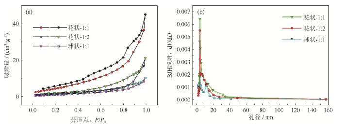
图 3 不同硫化钴样品的N2吸附‒脱附等温线(a)和孔径分布(b)
Figure 3. N2 desorption‒sorption isotherms (a) and pore distribution (b) of different cobalt sulfide samples
![]()
图 4 硫化钴电极材料倍率性能图
Figure 4. Specifc discharge capacities at various current rates of cobalt sulfide electrode materials
![]()
图 5 CoS负极材料循环伏安曲线:(a)0.5 mV·s‒1,CoS负极材料;(b)0.1~10 mV·s-1扫速,花状-1:1试样
Figure 5. CV curves of CoS electrode materials: (a) CoS electrode materials at 0.5 mV·s‒1; (b) flower-like sample-1:1 at the scan rates ranging from 0.1 to 10 mV·s‒1
![]()
图 6 CoS电极材料在0.1C的电流密度下首次充放电的电化学性能图
Figure 6. Electrochemical performance of initial charge–discharge curves at 0.1C of CoS electrode materials
![]()
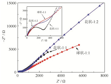
图 7 CoS电极材料的交流阻抗图
Figure 7. Electrochemical impedance spectra of CoS electrode materials
![]()
图 8 CoS电极材料在1C的电流密度下从0.05~3.0 V循坏性能曲线
Figure 8. Cycling performance curves of CoS electrode materials at 1C from 0.05 V to 3.0 V
表 1 硫化钴样品的比表面积和孔体积数值
Table 1 Specific surface area and pore volume of cobalt sulfide samples
试样 比表面积/ (m2·g‒1) 孔体积/ (mL·g‒1) 花状-1:1 15.3611 0.0593 花状-1:2 6.2693 0.0364 球状-1:1 4.1639 0.0180  下载: 导出CSV
表 2 CoS电极材料阻抗参数
Table 2 Impedance parameters of CoS electrode materials
试样 欧姆电阻/ Ω 传荷电阻/ Ω 阻抗总和/ Ω 花状-1:1 1.75 175.12 176.87 球状-1:1 9.17 377.67 386.84 花状-1:2 1.82 242.73 244.55
下载: 导出CSV
-
[1] Pasquariello D M, Kershaw R, Passaretti J D, et al. Low-temperature synthesis and properties of cobalt sulfide (Co9S8), nickel sulfide (Ni3S2), and iron sulfide (Fe7S8). Prep Inorg Chem, 1984, 15(25): 872 DOI: 10.1002/chin.198425040
[2] Yuan C Z, Gao B, Su L H, et al. Electrochemically induced phase transformation and charge-storage mechanism of amorphous CoSx nanoparticles prepared by interface-hydrothermal method. J Electrochem Soc, 2009, 156(3): A199 DOI: 10.1149/1.3065086
[3] Bao S J, Li Y B, Li C M, et al. Shape evolution and magnetic properties of cobalt sulfide. Cryst Growth Des, 2008, 8(10): 3745 DOI: 10.1021/cg800381e
[4] 刘淑敏. 过渡金属硫化物及其复合材料的合成和电化学性能研究[学位论文]. 长春: 长春理工大学, 2014 Liu S M. Synthesis and Electrochemical Properties of Transition Metal Sulfides and their Composite Materials[Dissertation]. Changchun: Changchun University of Science and Technology, 2014
[5] Wang Y M, Wu J J, Tang Y F, et al. Phase-controlled synthesis of cobalt sulfides for lithium ion batteries. ACS Appl Mater Interfaces, 2012, 4(8): 4246 DOI: 10.1021/am300951f
[6] 韩超伟. 石墨烯复合过渡金属硫化物作为锂离子电池负极材料的研究[学位论文]. 芜湖: 安徽师范大学, 2016 Han W C. Composites of Graphene and Transition Metal Sulfides as Anode Materials for Lithium Ion Batteries[Dissertation]. Wuhu: Anhwei Normal University, 2016
[7] Zhang C F, Wu H B, Guo Z P, et al. Facile synthesis of carbon-coated MoS2 nanorods with enhanced lithium storage properties. Electrochem Commun, 2012, 20: 7 DOI: 10.1016/j.elecom.2012.03.039
[8] Zhou Y L, Yan D, Xu H Y, et al. Multiwalled carbon nanotube@a-C@Co9S8 nanocomposites: a high-capacity and long-life anode material for advanced lithium ion batteries. Nanoscale, 2015, 7(8): 3520 DOI: 10.1039/C4NR07143C
[9] Débart A, Dupont L, Patrice R, et al. Reactivity of transition metal (Co, Ni, Cu) sulphides versus lithium: the intriguing case of the copper sulphide. Solid State Sci, 2006, 8(6): 640 DOI: 10.1016/j.solidstatesciences.2006.01.013
[10] Wang J, Ng S H, Wang G X, et al. Synthesis and characterization of nanosize cobalt sulfide for rechargeable lithium batteries. J Power Sources, 2006, 159(1): 287 DOI: 10.1016/j.jpowsour.2006.04.092
[11] Gómez-Cámer J L, Martin F, Morales J, et al. Precipitation of CoS vs ceramic synthesis for improved performance in lithium cells. J Electrochem Soc, 2008, 155(3): A189 DOI: 10.1149/1.2825137
[12] Wang Q H, Jiao L F, Han Y, et al. CoS2 hollow spheres: fabrication and their application in lithium-ion batteries. J Phys Chem C, 2011, 115(16): 8300 DOI: 10.1021/jp111626a
[13] Gu Y, Xu Y, Wang Y. Graphene-wrapped CoS nanoparticles for high-capacity lithium-ion storage. ACS Appl Mater Interfaces, 2013, 5(3): 801 DOI: 10.1021/am3023652
[14] Seo J W, Jang J T, Park S W, et al. Two-dimensional SnS2 nanoplates with extraordinary high discharge capacity for lithium ion batteries. Adv Mater, 2010, 20(22): 4269 http://pubs.rsc.org/en/Content/OpenURL/50003391/C3EE42591F/107_1
[15] Fan Y, Shao H, Wang J, et al. Synthesis of foam-like freestanding Co3O4 nanosheets with enhanced electrochemical activities. Chem Commun, 2011, 47(12): 3469 DOI: 10.1039/c0cc05383j
[16] Zhao L, Tao F Q, Quan Z, et al. Bubble template synthesis of copper sulfide hollow spheres and their applications in lithium ion battery. Mater Lett, 2012, 68(1): 28 http://www.sciencedirect.com/science/article/pii/S0167577X11011384
[17] Du N, Zhang H, Chen J E, et al. Metal oxide and sulfide hollow spheres: layer-by-layer synthesis and their application in lithium-ion battery. J Phys Chem B, 2008, 112(47): 14836 DOI: 10.1021/jp8065376
[18] Hu S, Chen W, Zhou J, et al. Preparation of carbon coated MoS2 flower-like nanostructure with self-assembled nanosheets as high-performance lithium-ion battery anodes. J Mater Chem A, 2014, 2(21): 7862 DOI: 10.1039/c4ta01247j
[19] Jin R C, Li G H, Zhang Z J, et al. Carbon coated flower like Bi2S3 grown on nickel foam as binder-free electrodes for electrochemical hydrogen and Li-ion storage capacities. Electrochim Acta, 2015, 173: 458 DOI: 10.1016/j.electacta.2015.05.021
[20] Stoller M D, Park S J, Zhu Y W, et al. Graphene-based ultracapacitors. Nano Lett, 2008, 8(10): 3498 DOI: 10.1021/nl802558y
[21] Lee C G, Wei X D, Kysar J W, et al. Measurement of the elastic properties and intrinsic strength of monolayer graphene. Science, 2008, 321(5887): 385 DOI: 10.1126/science.1157996
[22] Aboulaich A, Lorret O, Boury B, et al. Surfactant-free organo-soluble silica-titania and silica nanoparticles. Chem Mater, 2009, 21(13): 2577 DOI: 10.1021/cm900291p
[23] Kim Y S, Goodenough J B. Lithium insertion into transition-metal monosulfides: tuning the position of the metal 4s band. J Phys Chem C, 2008, 112(38): 15060 DOI: 10.1021/jp8038847
[24] Wang Q H, Jiao L F, Du H M, et al. Novel flower-like CoS hierarchitectures: one-pot synthesis and electrochemical properties. J Mater Chem, 2010, 21(2): 327 http://pubs.rsc.org/en/content/articlelanding/2011/jm/c0jm03121f
[25] Qiu W D, Jiao J Q, Xia J, et al. A self-standing and flexible electrode of yolk-shell CoS2 spheres encapsulated with nitrogen-doped graphene for high-performance lithium-ion batteries. Chemistry, 2015, 21(11): 4359 DOI: 10.1002/chem.201405821
[26] Xie J, Liu S Y, Cao G S, et al. Self-assembly of CoS2/graphene nanoarchitecture by a facile one-pot route and its improved electrochemical Li-storage properties. Nano Energy, 2013, 2(1): 49 DOI: 10.1016/j.nanoen.2012.07.010
-
期刊类型引用(3)
1. 祁进坤,岳永文,胡剑,赵钢,寇晓磊,齐国强,王宏升,任淑彬. 淬火温度对S590粉末冶金高速钢组织和性能的影响. 粉末冶金技术. 2024(01): 75-83 .  本站查看
本站查看
2. 刘文彬,乔龙阳,潘新宇,程格,李爱娜,裴新军. 淬火温度对刀剪用M390粉末冶金不锈钢组织和性能的影响. 金属热处理. 2022(04): 189-195 . 百度学术
3. 谭大庆,姜山,胡韶华,杨洪. 载荷对非自耗真空熔炼GC2025高硬刀具的滑动磨损行为的影响. 真空科学与技术学报. 2021(05): 477-481 . 百度学术
其他类型引用(4)


计量
- 文章访问数: 684
- HTML全文浏览量: 170
- PDF下载量: 39
- 被引次数: 7
